
Programming Manual

i480e&i480e-MD2 Programming Manual
30 / 139
1, Master mode, Clock and sync will be generated by the
I2S hardware.
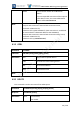
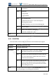
Justify
I2S format
0, left justified
1, right justified
Delay
Left justified format
0, MSB of SD data occurs in the first SCK period
following WS transition
1 MSB of SD data occurs in the second SCK period
Bits
bits per sample
Scale
master clock frequency scaling factor
clock rate = sample rate * scale
Note
N/A
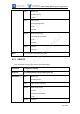
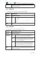
4.26
PIOSETPIN
This command is used to modify the contents of the PIO data output register.
Command
AT+B PIOSETPIN [mask], [bits]
Response
AT-B PIOSETPIN [result]
Parameters
result
A 32 bit mask. If any bit in this mask is high then that
PIO could not be driven to the level specified
mask
Each bit in the mask corresponds to a PIO line. Bits set
to 1 in this mask will be modified. Bits set to 0 in this
mask will not be modified.
bits
Each bit in the bits value corresponds to a PIO line. Bits
set to 1 in this value will result in that PIO line being
driven high. Bits set to 0 in this value will result in that
PIO line being driven low.
Note
1 PIO pins must be set to outputs via AT+B PIOSETDIR before they
can be driven high or low through this command.
Barrot Confidential