
Programming Manual

i480e&i480e-MD2 Programming Manual
34 / 139
(PIO 19) maps to the PCM_SYNC pin. This can be configured as an
input or an output.
(PIO 20) maps to the PCM_CLK pin. This can be configured as an
input or an output.
(PIO 21) maps to the SQIF Flash Clock pin. This can be configured as
an input or an output.
(PIO 22) maps to the SQIF RAM Clock pin. This can be configured as
an input or an output.
(PIO 23) maps to the SQIF Flash CS pin. This can be configured as an
input or an output.
(PIO 24) maps to the SQIF RAM CS pin. This can be configured as an
input or an output.
(PIO 25) maps to the SQIF DB0 pin. This can be configured as an
input or an output.
(PIO 26) maps to the SQIF DB1 pin. This can be configured as an
input or an output.
(PIO 27) maps to the SQIF DB2 pin. This can be configured as an
input or an output.
(PIO 28) maps to the SQIF DB3 pin. This can be configured as an
input or an output.
PIO lines above 28 map to nothing and cannot be mapped or
written.
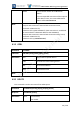
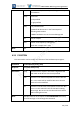
4.31
PIOGETMAP
This command is used to get which PIO lines have been mapped to chip pins.
Command
AT+B PIOGETMAP
Response
AT-B PIOGETMAP [result]
Parameters
result
A 32 bit value showing which PIO lines have been
mapped to chip pins.
Note
N/A
Barrot Confidential