POLARIS Remote User Manual Version 4.00 POLARIS Remote 19.1" / POLARIS Remote 15" Type 17-71V2-....
User Manual POLARIS Remote 19.1'' / Remote 15'' Version 4.00 Document No. 11-71V2-7D0011 INDEX A / Status: 7. November 2006 Technical data subject to change! (UK) Ltd. Station Road Facit Whitworth, Near Rochdale Lancashire, OL12 8LJ England Phone: Fax: Email: Internet: +44 17 06 85 22 24 +44 17 06 85 25 21 info@bartec.co.uk www.bartec.co.uk GmbH Max-Eyth-Straße 16 97980 Bad Mergentheim Deutschland Telefon : Telefax : E-Mail: Internet: +49 7931 597-0 +49 7931 597-183 support-polaris@bartec.de www.
Contents 1. System description .....................................................................................................................................8 2. Technical data POLARIS Remote ............................................................................................................10 3. 4. 5. 2.1 Characteristics data Remote 19.1'' und Remote 15'' ..................................................................10 2.2 General data...........................................
Contents 6. Installation of additional components.....................................................................................................25 6.1 Local unit for STP cable .............................................................................................................25 6.1.1 Features .....................................................................................................................................25 6.1.2 Operation ............................................
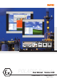
POLARIS Remote 19.1" / Remote 15" User manual 1. System description POLARIS Remote 19.1'' Keyboard POLARIS Remote 15'' Mouse Trackball Touchpad The POLARIS Remote 19.1" and POLARIS Remote 15" from BARTEC are displays with keyboard and mouse with which a PC in the non-hazardous area can be operated from the Ex zone (Zone 1). Distances are possible up to 10,000 m and depends on the variant.
POLARIS Remote 19,1" / Remote 15" The front panel fitting permits easy installation. On request, the devices can also be supplied in the form of complete system solutions in a stainless steel enclosure for wall, floor or ceiling mounted installation. Example: POLARIS Remote with stand Example: POLARIS Remote with Fibre optic The POLARIS Remote 19.
POLARIS Remote 19.1" / Remote 15" User manual 2. Technical data POLARIS Remote 2.1 Characteristics data Remote 19.1'' und Remote 15'' Type : 17-71V2-.... Ex protection type : e II 2G Ex e q [ib] IIC T4 e II 2D Ex tD A21 IP 6X T 80°C Certification 2.
POLARIS Remote 19.1" / Remote 15" 2.3 Characteristics data Remote 19.1'' Display : 19.1" TFT graphic display SXGA resolution 1280 x 1024 pixels 16.7 million colours Brightness 250 cd/m2 Visible area approx. 380 x 305 mm Contrast 700:1 Antireflection coating glass pane Optional touch screen (resistive) Dimensions : 498 mm x 400.5 mm x approx. 135 mm Wall cut-out : 484 mm x 386.5 mm + 0.5 mm Weight : approx. 33 kg Backlight illumination : CFL technology Service-life approx.
POLARIS Remote 19.1" / Remote 15" User manual 2.4 Characteristics data Remote 15'' Display : 15" TFT graphic display XGA resolution 1024 x 768 pixels 262,144 colours Brightness 350 cd/m2 Visible area approx. 304 x 228 mm Contrast 400:1 Antireflection coating glass pane Optional touch screen (resistive) Dimensions : 411 mm x 332 mm x approx. 135 mm Wall cut-out : 394.5 mm x 315.5 mm + 0.5 mm Weight : approx. 23 kg Backlight illumination : CFL technology Service-life approx.
POLARIS Remote 19.1" / Remote 15" Characteristics data keyboard Type : 17-71VZ-40.. Ex protection type : e II 2G Ex ib IIC T4 e II 2D Ex ibD 21 T 120°C Certification : IBExU05ATEX1117 X Protection class : IP 65 (front side) Construction : Front panel fitting Material Polyester foil on aluminium sheet (conditionally UV resistant) Dimensions : 420 mm x 170 mm (weight x height) Wall cut-out : 390 mm x 140 mm Installation depth : 18 mm Weight : approx.
POLARIS Remote 19.1" / Remote 15" User manual 2.6 Characteristics data mouse, trackball and touchpad 2.6.1 Mouse Type Ex protection type : : 17-71VZ-1000 e II 2G Ex ib IIC T4 e II 2D Ex ibD 21 T 120°C 2.6.
POLARIS Remote 19.1" / Remote 15" Dimensions and wall cut-out for mouse, trackball and touchpad 110.00 mm 170.00 mm 140.00 mm 85.00 mm 150.00 mm 100.00 mm 3.30 mm 130.00 mm All hole diameter: 3.
POLARIS Remote 19.1" / Remote 15" User manual 3. Terminal assignment 3.1 Overview of connections Sealed screw plug. Do not open! Label of tpye Ex i Terminal chamber Terminal X1-X9 USB plug for USB Stick Ex e Terminal chamber Terminal X10-X20 ST plug for connection to local unit (only at POLARIS Remote with fibre optic) 3.
POLARIS Remote 19.1" / Remote 15" 3.
User manual 3.3.1 POLARIS Remote 19.1" / Remote 15" Interference suppression Certain basic measures must be taken to ensure freedom from interference when the POLARIS Remote are installed: 18 Page 18 ■ Interference voltages injected into the unit via power and signal cables and static charges caused by contact are to be conducted to earth (e.g. grounding screw terminal fixed to the back of the unit).
POLARIS Remote 19.1" / Remote 15" 4. Overview of connection diagram 4.1 Standard application – Point-to-Point or fibre optic cable 4.2 Special application – Cascade circuit Cascading possible for up to 4 POLARIS Remote. Note: The local unit needs a separate external power supply (type no. see chapter 7 Accessories) PC VGA PS/2 keyboard PS/2 mouse Patch cable Local unit Connection box system RJ 45 STP CAT.5, CAT.6 or CAT.
POLARIS Remote 19.1" / Remote 15" User manual 5. Notes on the installation of POLARIS Remote 5.1 Safety instructions For electrical appliances, the appropriate regulations for setting-up and operation have to be observed (e.g. directive 1999/92/EC, directive 94/9EC, BetrSichV and national regulations/acts, IEC/EN 60 079-14 and VDE 0100).
POLARIS Remote 19.1" / Remote 15" 5.3 Installation options The POLARIS Remote can be installed directly in ■ ■ ■ Switch cabinet doors Mimic panels Enclosures In order to guarantee IP 65, use the reinforcement frame and the enclosure’s own IP rating has to be suitable for the application. The following points should be taken into consideration when installing the POLARIS Remote: Note: ■ ■ ■ ■ ■ Convenient height for operation.
User manual 5.4 POLARIS Remote 19.1" / Remote 15" Mechanical installation In order to achieve an even clamping pressure, it is recommended that the reinforcement frame (not included in the scope of the delivery) be inserted between the mounting clamps (included in scope of the delivery) and the enclosure. ■ ■ ■ 5.4.1 Tighten the fixing screws in the mounting brackets slightly. Check the position of the display and the seal.
POLARIS Remote 19.1" / Remote 15" 5.4.4 General data ■ The user is allowed to perform only the wiring work necessary on the terminals accessible to him. Any more extensive dismantling of the device may be performed only by the manufacturer or by persons authorized by the manufacture. The unit is factory sealed. Do not open! ■ Ex i-terminal compartment marked: with terminals for Ex i input device (Ex i-data) - Keyboard Type 17-71VZ-40..
User manual 5.4.5 24 Page 24 POLARIS Remote 19.1" / Remote 15" Installation guidelines ■ The external earth connection facility should be connected to the equipotential bonding conductor of the potentially explosive area. Since the intrinsically safe circuits are direct-connected to earth, equipotential bonding must be maintained during complete installation of the intrinsically safe circuits. ■ All current safety and accident prevention regulations must be observed.
POLARIS Remote 19.1" / Remote 15" 6. Installation of additional components 6.1 Local unit for STP cable Front panel Rear panel The SDBX-Cat5-KVM Extender "local unit" from IHSE GmbH can be used with the POLARIS Remote. Further information can be found in the Internet at: Data sheet: http://www.ihse.com/pdf/i434-Sx_e.pdf Manual: http://www.ihse.com/pdf/b434-Sx_e.pdf Please read the manual carefully and also pay attention on the warning of the manufacturer. 6.1.
User manual 6.1.2 POLARIS Remote 19.1" / Remote 15" Operation The local unit is simple to operate and works with all operating systems – no software is required. Just connect the units up as described and you’re ready to work. Complete keyboard and PS/2 mouse emulation allows you to ‘Plug & Play’. Your PC will boot even if the POLARIS Remote end of the link is not powered or the keyboard and / or mouse are disconnected. 6.1.
POLARIS Remote 19.1" / Remote 15" 6.1.4 Technical data "Local unit" Power supply Local unit : Optional, via the PC connected, thanks to additional table-top power pack Note: For cascading please take attention to chapter 4.2.
POLARIS Remote 19.1" / Remote 15" User manual The local unit is compatible with the following devices: PC PC/AT, PS2 and 100% compatible clones Keyboard PC/AT enhanced keyboard. Some older XT/AT autosensing keyboards may not be compatible. PS/2 mouse Standard PS/2 mouse, Microsoft Intellimouse, Logitech three-button mouse Monitor SVGA, VGA, XGA, RGB (Sync on Green) 6.1.6 The local unit is compatible with the following devices: ■ Connect the local unit to the PC and the two devices using a CAT.
POLARIS Remote 19.1" / Remote 15" 6.1.7 Quick Startup For advanced users, we recommend to take an overview over the system, by reading the ‘Quick Startup’ section: ■ ■ ■ Turn off your PC. Connect the POLARIS Remote to the voltage supply! ■ ■ ■ ■ Check the link integrity (LED at the local unit - flashing). ■ With cables, 100m+ it might be possible to obtain a better screen picture by processing Quick Skew – Toggle GREEN Delay (t + J) . ■ Exit Command Mode and save settings } .
POLARIS Remote 19.1" / Remote 15" User manual 6.2 Local unit for Fibre optic cable DMXI KVM-Extender DDXI KVM-Extender The DMXI or DDXI-KVM Extender "local unit" from IHSE GmbH can be used with the POLARIS Remote. Note: The DMXI local unit is used only in combination with POLARIS Remote without touch screen and without a power supply unit for BCS 302ex Hand-held scanner. Further information can be found in the Internet at: DMXI DDXI Data sheet: http://www.ihse.de/pdf/i421-xx_e.
POLARIS Remote 19.1" / Remote 15" 6.2.2 Operation The local unit is simple to operate and works with all operating systems – no software is required. Just connect the units up as described and you’re ready to work. Complete keyboard and PS/2 mouse emulation allows you to ‘Plug & Play’. Your PC will boot even if the POLARIS Remote end of the link is not powered or the keyboard and / or mouse are disconnected. 6.2.
POLARIS Remote 19.1" / Remote 15" User manual 6.2.4 Technical data "Local unit" Power supply Local unit : Power supply unit: AC 90 up to 240 V / 0.
POLARIS Remote 19.1" / Remote 15" The local unit is compatible with the following devices: PC PC/AT, PS2 and 100% compatible clones Keyboard PC/AT enhanced keyboard. Some older XT/AT autosensing keyboards may not be compatible. PS/2 mouse Standard PS/2 mouse, Microsoft Intellimouse, Logitech three-button mouse Monitor SVGA, VGA, XGA, RGB (Sync on Green) 6.2.6 The local unit is compatible with the following devices: ■ Connect the local unit to the PC and the two devices with two fibers 62.
POLARIS Remote 19.1" / Remote 15" User manual 6.3 Connection of EEx i keyboard to the POLARIS Remote ■ Make the connection between the POLARIS Remote and the EEx i keyboard. ■ Connection via connecting cable, longer than approx. 1.80 m - Keyboard and mouse Type 05-0068-0163 - Keyboard and trackball Type 05-0068-0172 - Keyboard and touchpad Type 05-0068-0183 6.4 Connection to BCS 302ex Hand-held scanner 6.4.
POLARIS Remote 19.1" / Remote 15" 6.4.2 Via RS232 ■ ■ 6.4.3 For serial interface connection at local unit see illustration in chapter 6.6. Configuration BCS 302ex see Original Symbol Manual. Via PS/2 ■ ■ ■ For keyboard wedge connection at local unit see illustration in chapter 6.6. For BCS 302ex configuration see Original Symbol Manual. To program the BCS 302ex hand-held scanner for keyboard wedge (type 17-28BB-0001) and to program the keyboard wedge, see Appendix.
User manual 6.5 POLARIS Remote 19.
POLARIS Remote 19.
POLARIS Remote 19.1" / Remote 15" User manual 6.6 Set up touch screen e.g. Local unit for CAT cable Serial connection to the PC Note the remarks in the manual on the enclosed CD (readmee.pdf) Install the touch driver (DMC, TSC-10 series, Serial) to the PC from enclosed CD or download it from www.dmccoltd.com/english/download/index.asp Available drivers: - Windows 95, 98, ME NT4, 2000 - Windows XP Connect serial port of local unit to COM port (9 pole) on PC.
POLARIS Remote 19.1" / Remote 15" 7. Accessories Designation Order no.
POLARIS Remote 19.1" / Remote 15" User manual 8. Order numbers POLARIS Remote 17-71V2- 0 4 5 6 7 / 00 15" 19.1" 15" with touch screen 19.1" with touch screen 0 0 0 1 0 4 8 2 STP cable STP cable; supply module for BCS 302ex Hand-held scanner Fibre optic (up to 400 m) Fibre optic (up to 400 m); supply module for BCS 302ex Hand-held scanner +1 = additional with keyboard and trackball e.g.
EC-Declaration of Conformity Page 4141
EG-Baumusterprüfbescheinigung 42 Page 42
EG-Baumusterprüfbescheinigung Page 4343
EG-Baumusterprüfbescheinigung 44 Page 44
EG-Baumusterprüfbescheinigung Page 4545
EC-Type Examination Certificate 46 Page 46
EC-Type Examination Certificate Page 4747
EC-Type Examination Certificate 48 Page 48
EC-Type Examination Certificate Page 4949
Additional technical information Mounting instructions Class D/E, CAT 6 Outlet 1. Preparation of the cable ends Remove cable sheathing approx. 50 mm in length. Cut back overall screen to approximate 15 mm, remove twisted pair screen as required. To ensure contact of the screen the diameter of the cable end must be 6 to 10 mm. If cable is too thin fold back screen over cable cover. To improve contact wind self-adhesive screening foil over the screen (approx. 2 turns, optional), bend tracing wire over that.
Additional technical information Mounting instructions Class D/E, CAT 6 Outlet 4. Wire connection Connect the connecting blocks with the LSA-Plus tool. The twist should be opened sufficiently to connect (max. 13 mm) 5. Mounting the bottom case Fit the notches of the top case into the slots of the bottom case and fasten. 6. Mounting the central insert 7.
Additional technical information Programming Keyboard wedge Programming the BCS 302ex Hand-held scanner: ■ Instruction manual from Symbol for programming (product reference guide for P300 STD/FZY/PRO scanner) ■ ■ ■ BCS 302ex Hand-held scanner Keyboard wedge Master BB+ with instruction manual Ready-connected and operative system Required barcodes in the manual: 52 Page 52 ■ ■ ■ ■ ■ Page 2 – 9 Barcode Set All Defaults Page 2 – 12 Barcode Standard RS – 232 C Page 2 – 16 Barcode Continous On Page
Additional technical information Default configuration of the keyboard wedge By reading in this barcode the keyboard wedge is returned to its standard setting. After scanning, wait approx. 6 sec until acknowledged. A G 0 Configuration start: $ % / In order to programme the keyboard wedge this special start sequence must be scanned at the beginning.
Additional technical information 54 Page 54
Transport and shipment Important Note concerning transport and shipping ! Sensitive Devices ! It is absolutely necessary to deliver the equipment in the original packaging in order to avoid damage occuring with the equipment. Order no. original packaging Order no. for Remote 15" 04-9035-0007 Order no. for Remote 19.
Return processing Return Form for Repairs Please note that it is essential to fill in this form and enclose it with the return shipment, as otherwise delays may occur in the processing of your order! Send to: Address of sender: BARTEC GmbH Service- und Retourencenter Max-Eyth-Straße 16 97980 Bad Mergentheim ........................................................................................... DEUTSCHLAND/GERMANY .....................................................................................
BARTEC protects people and the environment by the safety of components, s y s t e m s BARTEC GmbH Germany plants. Max-Eyth-Straße 16 97980 Bad Mergentheim Phone: +49 7931 597-0 Fax: +49 7931 597-119 info@bartec.de www.bartec-group.