
Datasheet

Josef Barthelme GmbH & Co. KG
Oedenberger Straße 149
D-90491 Nürnberg
www.barthelme.de
info@barthelme.de
Technische Änderungen und Irrtümer vorbehalten. / Subject to technical changes and errors.
Datum / Date: 06.2016 AST Revision: 1.0 Seite 2 von 2
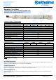
Application area
•Cove lighting •Architectural lighting •Backlight for letter lighting •Fair lighting •Stairway accent lighting •Bar lighting and a lot more.
Montagehinweis
− Die Kontaktierung erfolgt durch Anlöten der Zuleitungen an den vorgesehenen Lötpads (Beschriftung + / - beachten).
− Beim Löten ist die max. Lötdauer von < 10s und eine max. Löttemperatur von < 260°C einzuhalten.
− Das Trennen des Bandes ist jeweils nach 100mm zwischen den Lötpads durch Schneiden mit einer Schere o.ä. möglich.
− Die Montage des Moduls erfolgt mit dem rückseitig angebrachten doppelseitigen Klebeband und sollte wegen der Wärmeableitung
möglichst auf einer metallischen Oberfläche erfolgen. Achten Sie dabei auf saubere Oberflächen, die frei von Fett, Öl, Silikon und
Schmutzpartikeln sein müssen. Von einer Montage auf unebenen oder schlecht wärmeleitenden Oberflächen wie z. B. Rigips, Tapete, Holz
oder Stein wird ausdrücklich abgeraten, da dies die Lebensdauer erheblich reduziert und evtl. die Haftung des Klebebandes beeinträchtigt.
− Die Befestigungsmaterialien müssen in sich fest sein.
− Der minimale Biegeradius beträgt etwa 2cm.
Mounting advice
− Feeding by soldering at the designated solder pads (pay attention to the polarity + / -).
− When soldering, please be aware of the max. duration of < 10s and a max. soldering temperature of < 260°C.
− You can cut the stripe every 100mm between the solder pads on the marked points by using a pair of scissors or similar.
− With the double-adhesive tape on the back you can mount the modules. The installation of the stripe should be carried out if possible
on a metallic surface because of heat dissipation. Please pay attention to clean surfaces, which have to be free of oil, silicone and dirt
particles. An installation on uneven or poorly thermally conductive surfaces such as plasterboard, wallpaper, wood or stone is definitely
not recommended as significantly reduces the lifetime of the LEDs and possibly impairs the adhesion of the adhesive tape.
− Mounting material has to be solid in itself.
− The minimum bend radius is about 2cm.
Sicherheitshinweise
− Mechanische Belastungen der Bauteile auf den LED Modulen sind zu vermeiden
− Bei der Montage dürfen die Leiterbahnen nicht beschädigt oder unterbrochen werden!
− Nur eine Elektrofachkraft darf die Installation von LED Modulen (mit Netzgerät) unter Beachtung aller gültigen Vorschriften und Normen
vornehmen!
− Bitte Polung beachten! Bei falscher Polung erfolgt keine Lichtemission bzw. kann das LED Modul Schaden nehmen!
− Einen sicheren Betriebszustand ermöglicht nur die elektrische Parallelschaltung. Von der elektrischen Reihenschaltung der LED Module
wird ausdrücklich abgeraten.
− Unsymmetrische Spannungsabfälle können zu einer starken Überlastung und Zerstörung einzelner Module führen.
− Bei der Montage auf metallischen Flächen ist zur Vermeidung von Kurzschlüssen an der Stelle der Lötkontakte eine Isolation zwischen
Montagefläche und Modul vorzusehen.
− Die maximale Länge eines zusammenhängenden LED Moduls beträgt 5,0m. Entsprechend längere LED Module sind durch
Zwischeneinspeisung oder Einspeisung an Anfang und Ende des LED Moduls möglich.
− Auf Maßnahmen gegen ESD während der Montage ist zu achten.
− Korrosionsmängel durch Kontakt mit Feuchtigkeit oder Kondenswasser, werden nicht anerkannt.
− Der maximale Strom pro Rolle (max. Länge) beträgt kurzzeitig 3 Ampere. Bei Verwendung eines Netzgerätes mit einem Ausgangsstrom
von größer 3 Ampere sind die Module dementsprechend mit einer superflinken Sicherung abzusichern.
Safety notes
− Mechanical stresses of the devices on the LED modules are to be avoided!
− During the mounting process the PCB may not be damaged or interrupted.
− Only an electronically skilled person is allowed to do the installation of LED modules (with power supply) in consideration of all valid
instructions and norms.
− Please pay attention to the polarity! With an incorrect polarity, there will be no light emission or the LED module can be damaged!
− Only a secure operating state submits a parallel connection. Please avoid a series connection of the LED module. Unsymmetrical voltage
drop may cause a strong over-loading and destruction of single modules
− To avoid any short circuits at the solder patches by mounting on metallic surfaces, there should be an insulator between module and
mounting surface.
− The maximum length of an associated LED module is approximately 5.0 m. Longer LED modules can be obtained by intermediate
feeding or feeding at the beginning and end of the LED module.
− A sufficient cooling has to be respected, e.g. by sticking to metallic surfaces.
− Please be aware of ESD while mounting.
− Corrosion defects caused by the contact with condensation or humidity cannot be granted.
− The maximum current per reel (max. length) is 3 Ampere for a short time. When using a power supply with an output current of greater
than 3 Ampere, the modules must accordingly be fused with a super quick protection.