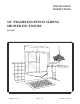
INSTALLATION INSTRUCTIONS 3/8” FRAMELESS BYPASS SLIDING SHOWER ENCLOSURE QCI-5017 QCI5017 Rev.
INSTALLATION NOTES: Unpack your unit carefully and inspect for freight damage. Lay out and identify all parts using the instruction sheet as a reference. Before discarding the carton, check to see that no small hardware parts have fallen to the bottom of the box. If any parts are damaged or missing, refer to the descriptions noted in the instructions when contacting your dealer for replacements. Handle the glass panel(s) carefully and protect the edges.
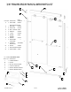
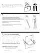
/8” FRAMELESS BYPASS SLIDER PARTS LIST G F A ITEM QTY DESRIPTION A 2 WALL JAMB B BOTTOM TRACK SC624 1 AND VINYL SCV190 C 6 WALL PLUG D 6 #8 X 2" SCREW SCR15 E 4 BUMPER SC4294 F 2 T-LOCK SC4339 G 4 HEADER HANGER 4 BRACKET SC623 H J LA0622 SC4106 SC1615 M 2 GLASS PANEL TOWEL BAR 2 ASSEMBLY HEAVY DUTY 4 ROLLER V 1 BOTTOM GUIDE SC4344 W 2 GUIDE SCREW K H PART NUMBER —- K SEE PAGE 6 SC4082 SCR24 G H—SC1615 EXPLODED VIEW ITEM QTY DESRIPTION L 1 HANGER BRACKET M N 1 1 ROLLER
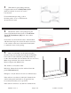
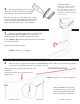
1 This framess bypass sliding enclosure is supplied with custom fit Wall Jambs [A]. The jambs are notched one end to fit over the bottom track. For maximum waterproofing, position the inner panel to close to wall where the shower head is located. 2 Measure the wall-to-wall opening along the center of the threshold at the bottom. Cut the Bottom Track (W/ Vinyl Silencer) [B] 1/16” short of that dimension. Position the bottom track in the center of the threshold with the raised edge to the exterior.
Alternative Method: SIL ICO 4 NE Before replacing the track, force a slight downward bow into it. This will ensure that the track fits tight to the threshold in the middle. Run 2 beads of silicone inside the pnecil marks on the threshold. Place the tub track in position over the silicone, lining it up with the pencil marks on the threshold from the previous step. Run a bead of silicone on both flat surfaces on the bottom of the track.
7 If not already attached, attach the Black Rollers [M] to the door Hanger Brackets [H]as shown using the #8-32 x 3/8” Hex Head Screws[N] . The rollers should be approximately in the center of the slots of the bracket fins. 8 From the outside of the shower, lift the inner panel into place with the rollers (and textured side of glass) facing you. Lower it into the shower and then lift it into the header. Be sure the bracket fins and rollers are above the track groove.
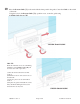
10 Place the Bottom Guide [V] on the track with the inner panel in the guide. Center the Guide on the width of the track. Using the holes in the Bottom Guide [V]to position r scews, secure the guide using . 2 SCR24 Guide Screws [W] VIEWED FROM INSIDE PRO-TIP: While the included screws are self drilling, installation of the Guide Screws [W] can be made easier with a pilot hole: 1) Slide the Center Guide into its final position. 2) Mark the location of the screw holes on the tub track.
11 Neatly silicone each end of the tub track where it fits into the wall jambs as well as the seam between the wall and the wall jamb and the curb and threshold on the inside of the shower. r. Optional: Silicone between the walls and wall jambs, and the curb and threshold on the outside of the shower. NOTE: DO NOT USE the shower until the silicone is completely cured. Check the tube of silicone for the manufacturer recommended cure time. (typically 24 - 48 hours) QCI5017 Rev.
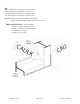
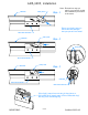
ANTI-JUMP, Installation HEADER ANTI-JUMP Note: Illustrations may not match your specific model, but installation procedure Step - 1 is the same. Place one Anti-Jump on each Bracket Hanger: two per panel: four total. BRACKET HANGER HEADER ANTI-JUMP Step - 2 ANTI-JUMP BRACKET HANGER HEADER ANTI-JUMP Step - 3 HEADER BRACKET HANGER BRACKET HANGER If the Anti-Jump does not stay in the place or if it is difficult to insert, snap off the "roller side leg" leaving one remaining leg. QCI5017 REV.