
User guide


REGISTERS READING A REGISTER
4 • ‘M’ SERIES WATER METERS
‘M’ SERIES WATER METERS • 5
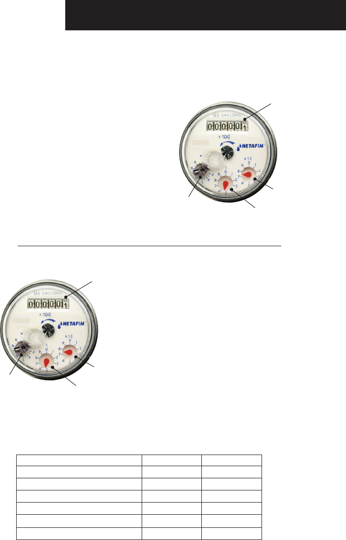
READING A REGISTER
The Total Flow for a Water Meter register is calculated by adding the readings from the Totalizer
and the three fractional dials. The three fractional dials measure quantities smaller than the
totalizer reading and are continuously turning while calculating the flow.
Totalizer Reading: 0 0 x 100 = 0
Fractional Dial # 1: 7 7 x 10 = 70
Fractional Dial # 2: 5 5 x 1 = 5
Fractional Dial # 3: 7 7 x 0.1 = .7
NOTE: If a number is partially visible on the totalizer,
always default to the lower of the 2 numbers when
calculating flow. If a fractional dial is pointing between
numbers, always default to the lower of the 2 numbers.
CALCULATION:
Add Totalizer Reading and all Fractional Dial
Readings
0 + 70 + 5 + .7 = 75.7 U.S.G.
75.7 U.S. Gallons is the Current Total Flow
CALCULATING THE TOTAL FLOW FOR
THIS REGISTER
TOTALIZER READING: Rotates sequentially for
each 100 U.S.G. (U.S. Gallons) calculated
Number displayed is multiplied by 100 to reach
total U.S.G.
FRACTIONAL DIAL # 1: Each number (1-9) on
the dial is multiplied by 10 to reach U.S.G.
One complete revolution of this dial = 10 U.S.G.
FRACTIONAL DIAL # 2: Each number (1-9) on
the dial is multiplied by 1 to reach U.S.G.
One complete revolution of this dial = 1 U.S.G.
FRACTIONAL DIAL # 3: Each number (1-9) on
the dial is multiplied by 0.1 to reach U.S.G.
One complete revolution of this dial = 0.1 U.S.G.
Fractional
Dial #2
Fractional
Dial #3
Fractional
Dial #1
Totalizer
Reading
Fractional
Dial #2
Fractional
Dial #3
Fractional
Dial #1
Totalizer
Reading
GALLON
3/4” AND 1“
GALLON X 10
0.1
x 0.01 GALLON
x 0.1 GALLON
x 1.0 GALLON
GALLON
3/4” AND 1“
GALLON X 100
1.0
x 0.10 GALLON
x 1.0 GALLON
x 10 GALLON
REGISTER TOTALIZER
METER SIZE
VOLUME UNIT
PULSE OUTPUT (GALLONS/PULSE)
POINTER RESOLUTION - POINTER 1
POINTER RESOLUTION - POINTER 2
POINTER RESOLUTION - POINTER 3
REGISTER SPECIFICATIONS
REED SWITCH REGISTER
The Reed Switch Register is a dry contact or simple switch
closure for communicating with control and monitoring
equipment. Registers are interchangeable and easily
replaced with common tools. They are removable even when
the meter is operating. A leak indicator in the center of the
dial registers the lowest flow through the meter. Flows are
totalled in U.S. Gallons and each dial face indicates the
multiplication factor.
Magnetic coupling activates the reed switch
creating a pulsed output.
Dry contact uses very little electric power.
Calculates volume related functions such as
data recorders or simple counters.
Maximum contact current is 50mA and
maximum contact voltage is 48VDC.
Red Wire = Positive
Black Wire = Negative
PHOTO DIODE REGISTER
The Photo Diode Register has a photo coupler
sensor that provides pulse output for communicating
with control and monitoring equipment. Registers are
interchangeable and easily replaced with common tools.
They are removable even when the meter is operating.
Flows are totalled in U.S. Gallons and each dial face
indicates the multiplication factor.
A sensor combines an IR light source and a light
sensitive diode in one package. Signals are created
when the light beam created by the IR light is
interrupted by a rotating element.
Requires a constant supply of DC power.
Minimum contact current is 15mA to a maximum of 25mA
DC through a resistor and maximum voltage is 28VDC.
Yellow Wire = Positive (20-30mA through a resistor)
Transparent Wire = Output (open collector, max. load 2mA)
Bare Wire = Ground
TRANSPARENT : OUTPUT (npn) - MAX 2mA-25V
SHIELD: GROUND MAX. VOLTAGE : 25 VDC
5 YELLOW-MIN 15mA - MAX 25mA DC
Black Wire
Red Wire
TRANSPARENT : OUTPUT (npn) - MAX 2mA-25V
SHIELD: GROUND MAX. VOLTAGE : 25 VDC
5 YELLOW-MIN 15mA - MAX 25mA DC
Yellow
Wire
Transparent
Wire
Bare
Wire
RESISTOR VALUE - Ω
RESISTOR VALUE - W
180
0.25
220
0.25
330
0.25
470
0.5
1,000
1.0
RECOMMENDED RESISTOR VALUES
VOLTAGE › 5
6
9 12 24
Note: Correct polarity
of the leads should be
checked carefully to
prevent damage of the
sensor. Register will not
function properly if the
register lid is not closed
during operation.
Reed
Switch
Only
NOTE: Always refer to the controller
manufacturer’s instructions for proper
installation and connection requirements.