
User guide


INSTALLATION MAINTENANCE
6 • ‘M’ SERIES WATER METERS
‘M’ SERIES WATER METERS • 7
MAINTENANCE REQUIREMENTS
1. Inlet side basket filter should be removed and cleaned every 90 days or as needed based on
the water quality at the site (see Figure 5).
2. Inlet side basket filter must remain in place during normal operation in order to avoid debris
entering and clogging the metering chamber.
3. Teflon tape should be used on pipe fittings and connections as needed to prevent leaks.
WARNING:
Units must not be subjected to system ‘blow out’ using compressed air. Subjecting the water
meter to this procedure will result in product failure and the resulting damage is not covered under
warranty. It is recommended that the water meter be installed in systems or portions of systems
that will gravity drain for winterization only.
If the unit is installed in a system which will be winterized with compressed air, please do one of
the following:
Install manual ball valves on each side of the water meter to isolate the water meter
from the system blow out procedure. Close the manual ball valve on one side of the
water meter, perform the blow out procedure and then open the manual ball valve.
Repeat process on the other side.
Remove the water meter before the blow out procedure and replace it with a section of
PVC/Polyethylene tubing. When the blow out procedure is complete, reinstall the water
meter.
FIGURE 5
Cleaning Inlet Side
Basket Filter
Inlet Side
Basket Filter
REGISTER REMOVAL AND INSTALLATION
1. Pry the tamper-proof tab upward using a screwdriver.
2. Loosen and unscrew the brass or plastic closing ring and cap assembly that secures the register.
Lift off the closing ring and cap assembly. Lift out the register from it’s sealed compartment making
note of the position for any spacers and o-rings.
3. To install, place the register into the sealed compartment (including spacers and o-rings) and
place the closing ring and cap assembly on top of the register. Tighten the closing ring by twisting
until secure.
INSTALLATION REQUIREMENTS
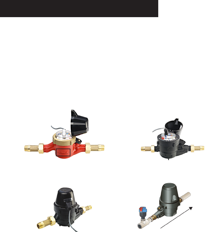
1. Correct direction of flow is indicated on the water meter body (see Figure 1).
2. Dial face must be horizontal and facing upwards (see Figure 2).
3. Register lid must be in the closed position during normal operation (see Figure 3).
4. There are no straight pipe installation requirements. If possible 5” of straight pipe upstream
(before the meter) and 2” of straight pipe downstream (after the meter) is recommended to
achieve the best performance and accuracy.
5. Prior to water meter installation, the pipeline should be thoroughly flushed.
6. The water meter must be installed so that the pipe will be full of water at all times during metering.
7. Installation of a Continuous Acting Air Vent before the water meter is highly recommended to
eliminate air and ensure accurate flow readings (see Figure 4). For additional details on air vent
options and installation requirements, refer to the Netafim USA Landscape & Turf Catalog.
FIGURE 2
Dial face upwards
↑
FIGURE 4
Air vent installation
Continuous
Acting Air Vent
Water Meter
Water Flow
‘M’ SERIES WATER METER WARRANTY
Netafim ‘M’ Series Water Meters are individually tested, calibrated and inspected to ensure they
meet the highest quality standards and the testing documents are included with each meter. They
also have the industry’s longest warranty.
3 YEARS
5 YEARS
METERING COMPONENTS
(REGISTER & METERING ASSEMBLY)
METER BODY
WARRANTY
FIGURE 1
Direction of flow
indicated on body
↑
FIGURE 3
Register lid closed