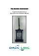
The Baseline Commander Irrigation Remote Control Operation and Installation Manual
Table of Contents INTRODUCTION .......................................................................................................... 3 WARRANTY ................................................................................................................. 3 FCC REGULATIONS .................................................................................................... 3 Models and Description ..................................................................................................
INTRODUCTION Congratulations! You have just purchased the most advanced irrigation remote control available - the Baseline Commander. We welcome you to the growing family of satisfied Baseline Irrigation product users who appreciate the importance of high standards, product quality and timely service. All of our remote control products do not require site surveys, base stations or FCC licensing. WARRANTY All Baseline Commander products carry a “THREE YEAR WARRANTY”.
Models and Description Transmitter Baseline Commander Transmitter is the hand-held part of your remote system. Any 24VAC solenoid valve sprinkler system equipped with a Baseline Commander or compatible Universal Receiver can be operated with this Transmitter. The Transmitter operates on one replaceable 9-volt alkaline battery. Note: The battery must be alkaline or the transmitter will not operate. Receivers Baseline Commander Mobile Receiver Units attach easily to the controller.
Special Features: • Connects to any 24VAC sprinkler system • Silent Running -Turn off all of the zones from 1 - 7 days • Adjustable Time Duration -2 Minutes to 2 Hours (default 20 minutes) • Multiple Receiver operation from a single Transmitter - Field programmable dipswitches offer 199 unique Receiver numbers • Programmable security codes -9999 different security group codes • Audible low power indicator -Field replaceable 9 volt battery • Master Valve disable key -Pump Start/Master Valve
Getting To Know the Transmitter The Baseline Commander Transmitter sends a proprietary FM signal to the Commander Receiver(s) turning on or off selected valves. With each valve activation or deactivation, the Pump Start/Master Valve station, when used, is automatically turned on or off unless "MV Off" has been pressed. The Transmitter is designed for minimal power consumption to extend the life of the battery. The Transmitter power is normally off.
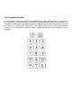
The Transmitter Key Pad The Commander Transmitter keypad has an audible beep to clearly indicate when a key is pressed. The Transmitter will beep once when a Number Key or the Receiver Number Key is pressed. The Transmitter will beep twice, with about two seconds between beeps, after a transmit key is pressed for ("VALVE ON", "VALVE OFF", "AUTO UP", "AUTO BACK", "M-V OFF" or "TIME").
Transmitter Operating Instructions Error Tone You will hear a “squawk” error tone if an incorrect series of keys has been pressed. When the error tone is heard, wait 10 seconds and simply restart the series of commands. Low Battery Tone A rapid sequence of beeps after the transmission beep indicates low battery power. Replace with a new alkaline 9V battery. Valve On/Valve Off To turn a valve on press the desired zone number and then press the "Valve On" key.
Auto Up/Auto Back These functions allow forward and backward advancement through each station. This will turn on the next sequential station number. To operate press: Multiple Zones Press the "9" key before a two digit zone number to turn on a multiple zone. Example: "903", "Valve On" will turn zone 3 on. You may have up to six multiple zones on at a time and a single zone plus a master valve.
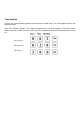
Time Duration You can set a time duration anywhere from two minutes to two hours. Press three digits of time in the following format: Hour, Tens Minutes, Minutes. The range of allowed entries for time duration is from two minutes "002" to two hours "200". Then press the "Time" key, followed by the desired zone # and then "Valve On.
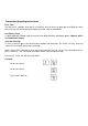
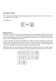
Reprogramming the Transmitter You must first wait at least 10 seconds after any key has been pressed before reprogramming. The following example reprograms the Transmitter to the factory defaults. YOU DO NOT NEED TO CHANGE ANYTHING TO MAKE YOUR UNITS OPERATE! Step 1: Step 2: Step 3: Step 1 gives you access to the Transmitter’s memory. Step 2 sets the Group Code to “0001”. Step 3 sets the Receiver Number to “1”.
Setting the Receiver’s Dip Switches YOU DO NOT NEED TO CHANGE ANYTHING TO MAKE YOUR UNITS OPERATE! The units come from the factory set on Group Code # 1, Receiver # 1. If you change the dipswitches, you must reprogram you transmitter to the same settings, as explained on the previous page.
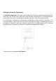
Installing the Mobile Receiver Connecting the Baseline Commander Mobile Receiver The Baseline Commander Receiver works with any Baseline BL3200 Series irrigation controller by plugging into the face plate of the BL3200X family of controllers and into the Mini-USB port of earlier controllers. For locations where minimal operating range is needed, connect the 8”whip antenna directly to the top of the Receiver.
Installing the Universal Receiver Connecting the Baseline Commander Universal Receiver The Baseline Commander Universal Receiver works with any 24VAC solenoid valve sprinkler system. The Baseline Universal Receiver connects to individual valves at the controller’s terminal strip or directly to the valve wires at the controller, and bypasses the controller’s functions by directly activating the valves. Once the connector is installed, simply plug the Receiver into the Black Receptacle.
Wiring Your Universal Receiver Connection System Instructions also provided with Universal Receiver Connection Assembly Warning Do not have the Receiver plugged into connector cable while installing connector or damage may occur. Do not have 24VAC transformer plugged into Receiver with the connector when the connector has 24VAC from the controller! Step 1: Use (figure 4 from the pamphlet with your PCC) as a pattern to locate the mounting holes to be drilled through the controller.
Trouble Shooting Chart Use the following chart to determine if your problem can be corrected in the field. If you have a problem that cannot be fixed in the field: • Call the toll free Baseline Customer Service number (866) 294-5847 and • You must obtain a Return Material Authorization RMA # prior to sending any unit in for repair. Fault Indication Correction A squawk from the transmitter • An improper key sequence has been entered and confused and then continue with a proper key sequence.
Optional Parts BL-CCBL Interface cable – One per BL3200 non-X versions. To be left attached to each controller. BL-PMBL Power Module used to power the Baseline Commander Mobile Receiver. Previous product generations do not provide power for the Baseline Commander Mobile Receiver and this power supply must be used to provide necessary power.
BL-CMDR-U Universal Receiver interfaces the Baseline Commander to non baseline clocks. One receiver is moved from clock to clock as required. BL-CMDR-UCON The wiring harness is permanently attached to each clock.
32 Station Connector Wiring Color Codes Valve 1 Black Wire Color Valve 19 Wire Color Green w/ black and white stripe 2 White 20 Orange w/ black and white stripe 3 Red 21 Blue w/ black and white stripe 4 Green 22 Black w/ red and green stripe 5 Orange 23 White w/ red and green stripe 6 Blue 24 Red w/ black and green stripe 7 White w/ black stripe 25 Green w/ black and orange stripe 8 Red w/ black stripe 26 Orange w/ black and green stripe 9 Green w/ black stripe 27 Blue w/
2700 E. Lanark St, Ste 100 Meridian, ID 83642 208-323-1634 direct 866-294-5847 toll free www.baselinesystems.