t f a r D A101f Camera User’s Manual Document ID Number: DA039104 Revision Date: May 20, 2002 Subject to Change Without Notice © Basler Vision Technologies Basler Support Worldwide: Americas: +1-877-934-8472 vc.support.usa@baslerweb.com www.basler-vc.com Europe: +49-4102-463-500 vc.support.europe@baslerweb.com Asia: +65-425-0472 vc.support.asia@baslerweb.
For customers in the U.S.A. This equipment has been tested and found to comply with the limits for a Class A digital device, pursuant to Part 15 of the FCC Rules. These limits are designed to provide reasonable protection against harmful interference when the equipment is operated in a commercial environment. This equipment generates, uses, and can radiate radio frequency energy and, if not installed and used in accordance with the instruction manual, may cause harmful interference to radio communications.
DRAFT Table of Contents 1 Introduction 1.1 Camera Models . . . . . . . . . . . . . . . . . . . . . . . . . . . . . . . . . . . . . . . . . . . . . . . . . . . 1-1 1.2 Performance Specifications . . . . . . . . . . . . . . . . . . . . . . . . . . . . . . . . . . . . . . . . . . 1-2 1.3 Environmental Requirements . . . . . . . . . . . . . . . . . . . . . . . . . . . . . . . . . . . . . . . . . 1-5 1.3.1 Temperature and Humidity . . . . . . . . . . . . . . . . . . . . . . . . . . . . . . . . . . . . . . 1-5 1.
DRAFT 3.10 Low Smear . . . . . . . . . . . . . . . . . . . . . . . . . . . . . . . . . . . . . . . . . . . . . . . . . . . . . 3-18 3.11 Color Creation in the A101fc . . . . . . . . . . . . . . . . . . . . . . . . . . . . . . . . . . . . . . . 3-20 3.11.1 White Balance . . . . . . . . . . . . . . . . . . . . . . . . . . . . . . . . . . . . . . . . . . . . . . 3-21 3.11.2 Using the A101fc in a Monochrome Mode . . . . . . . . . . . . . . . . . . . . . . . . 3-21 3.11.
DRAFT Introduction 1 Introduction The BASLER A101f progressive scan camera is a versatile camera designed for industrial use. Superb image sensing features are combined with a robust, high precision housing. Important features are: • Compliant with the 1394 TA Digital Camera Specification (V 1.
Introduction DRAFT 1.2 Performance Specifications Specification A101f Sensor Type Sony ICX085AL/AK - 2/3 inch, HAD, interline transfer, progressive scan CCD Pixels 1300 (H) x 1030 (V) Pixel Size 6.7 µm (H) x 6.7 µm (V) Anti-Blooming 1:100 Dark Signal Non-uniformity ± 1 DN Photo Response Non-uniformity ± 5% Max. Frame Rate (at full resolution) 12 frames/sec.
DRAFT Introduction The spectral responsivity for monochrome cameras is shown in Figure 1-1. The graph includes lens characteristics and excludes light source characteristics. 1.0 0.9 0.8 0.7 0.6 0.5 0.4 0.3 0.2 0.1 0.
DRAFT Introduction The spectral responsivity for color cameras is shown in Figure 1-2. The graph includes lens characteristics and excludes light source characteristics. 1 0.9 R B G 0.8 0.7 0.6 0.5 0.4 0.3 0.2 0.1 0 400 500 600 700 Wave Length [nm] Figure 1-2: Spectral Responsivity - Color Cameras * 1-4 Cameras equipped with a C-mount lens adapter contain an integrated IR cut filter.
DRAFT Introduction 1.3 Environmental Requirements 1.3.1 Temperature and Humidity Housing temperature during operation: 0° C … + 50° C (+ 32° F … +122° F) Humidity during operation: 20% … 80%, relative, non-condensing 1.3.2 Ventilation Allow sufficient air circulation around the camera to prevent internal heat build-up in your system and to keep the camera housing temperature below 50° C. Provide additional cooling such as fans or heat sinks if necessary.
Introduction 1-6 DRAFT BASLER A101f
DRAFT Camera Interface 2 Camera Interface 2.1 Connections 2.1.1 General Description The A101f is interfaced to external circuitry via an IEEE 1394 socket and a 9-pin micro-D plug located on the side of the housing. Figure 2-1 shows the location of the two connectors. There are also two status LEDs on the back of the camera. The LEDs indicate signal integrity and power OK (see Section 6.1).
DRAFT Camera Interface 2.1.2 Pin Assignments The IEEE 1394 socket is used to supply power to the camera and to interface video data and control signals. The pin assignments for the socket are shown in Table 2-1. Pin Signal Pin Signal 1 +12 VDC 4 TPB+ 2 DC Gnd 5 TPA- 3 TPB- 6 TPA+ Table 2-1: Pin Assignments for the IEEE 1394 Socket The 9-pin micro-D plug is used to interface the external trigger, integrate enabled, and trigger ready signals.
DRAFT Camera Interface 2.1.3 Connector Types The 6-pin connector on the camera is a standard IEEE-1394 socket. The 9-pin Micro-D plug is Molex Part Number 83611-9006 or the equivalent. 2.2 Video Data and Control Signals 2.2.1 Input Signals 2.2.1.1 ExTrig: Controls Exposure Start An external trigger (ExTrig) signal can be used to control the start of exposure. ExTrig can be a periodic or a non-periodic function.
DRAFT Camera Interface 2.2.2.3 Pixel Data Pixel data are transmitted as isochronous data packets according to version 1.20 of the “1394 based Digital Camera Specification” issued by the 1394 Trade Association. The first packet of each frame is identified by a 1 in the sync bit of the packet header. The video data for each pixel is output in an 8 bit format. Thus the range of intensity for each pixel includes 256 gray levels.
DRAFT Camera Interface 2.3 Camera Power Power must be supplied to the camera via the IEEE 1394 cable. The camera requires +12 VDC ± 10%. Maximum power consumption is 5.0 W for the A101f. Ripple must be less than 1%. 2.4 Status LEDs Green LED The green LED on the back of the camera is used to indicate whether power is being supplied to the camera. When the green LED is out, it means that no power is present. When the green LED is lit, it means that power is present.
Camera Interface 2-6 DRAFT BASLER A101f
DRAFT Operation and Features 3 Operation and Features 3.1 Functional Description The A101f area scan camera employs a CCD-sensor chip which provides features such as electronic exposure time control and anti-blooming. Normally, exposure time and charge readout are controlled by values transmitted to the camera’s control registers via the IEEE 1394 interface. Command registers are available to set exposure time and frame rate.
DRAFT Operation and Features CCD Sensor Vert. Shift Reg. ADC Pixels Vert. Shift Reg. Pixels Vert. Shift Reg. Pixels Vert. Shift Reg. Pixels VGC Horizontal Shift Register Figure 3-1: Sensor Architecture Microcontroller 1 Control: Shutter Binning AOI Gain Brtness.
DRAFT Operation and Features 3.2 Exposure Control 3.2.1 Setting the Exposure Time Exposure time is determined by the value stored in the SHUTTER control register. The value in the register can range from 0 to 4095 (0x000 to 0xFFF). The value in the register represents n in the equation: Exposure Time = (n + 1) x 20 µs. So, for example, if the value stored in the SHUTTER register is 100 (0x064), the exposure time will be (100 + 1) x 20 µs or 2020 µs. 3.2.
Operation and Features DRAFT If the camera is operating in video Format 7, the rate at which frames will be captured and transmitted is determined by the value stored in the BYTE_PER_PACKET control register (see Section 3.12.2). Frame exposure and transmission stop when the ISO_EN/CONTINUOUS_SHOT control register is set to 0. 3.2.3 Controlling Exposure Start with an ExTrig Signal The external trigger (ExTrig) input signal can be used to control the start of exposure.
DRAFT Operation and Features 3. Check the state of the TrigRdy signal: a) If TrigRdy is high, you can toggle ExTrig when desired. b) If TrigRdy is low, wait until TrigRdy goes high and then toggle ExTrig when desired. 4. When ExTrig goes high, exposure will begin. Exposure will continue for the length of time specified in the SHUTTER control register. 5. At the end of the specified exposure time, frame readout and transmission will take place. 6.
DRAFT Operation and Features Case 1 - Exposure Start When the Camera is not Transferring a Frame After each exposure is complete, there is a time period of 80.7 ms. during which the captured frame is transferred from the CCD sensor to the camera’s image buffer. If the ExTrig signal rises after this time period has ended as shown in Figure 3-3: • The start of exposure will occur between 3 and 6 µs after the rise of ExTrig.
DRAFT Operation and Features Case 2 - Exposure Start When the Camera is Transferring a Frame After each exposure is complete, there is a time period of 80.7 ms. during which the captured frame is transferred from the CCD sensor to the camera’s image buffer. If the ExTrig signal rises during this time period as shown in Figure 3-4: • The start of exposure will occur between 3 µs and 86 µs after the rise of ExTrig.
DRAFT Operation and Features 3.3 Trigger Ready Signal * The trigger ready signal is not defined in the 1394 Trade Association Digital Camera Specification. Trigger ready is a special feature of Basler cameras. One possible way to control the camera is to perform an image exposure followed by charge read out and frame transfer and to wait until frame transfer is complete before beginning the next exposure. This situation is illustrated in Figure 3-5.
DRAFT Operation and Features For better understanding of the use of trigger ready signal, consider an example. Assume that you will set the exposure time to 20 µs for every exposure and that you want to begin exposing as early as possible during transfer of the previous frame. In this case, the trigger ready signal will go high 20 µs before the earliest allowable end of exposure. This situation is illustrated in Figure 3-7.
Operation and Features DRAFT 3.4 Integrate Enabled Signal The Integrate Enabled (IntEn) signal goes high when exposure begins and goes low when exposure ends. This signal is especially useful when you are operating a system where either the camera or the object being imaged is movable. For example, assume that the camera is mounted on an arm mechanism and that the mechanism can be used to move the camera to view different portions of a product assembly.
DRAFT Operation and Features 3.6 Gain and Brightness The major components in the camera electronics include: a CCD sensor, a VGC (Variable Gain Control), and an ADC (Analog to Digital Converter). The pixels in the CCD sensor output voltage signals when they are exposed to light. These voltages are amplified by the VGC and transferred to the ADC which converts the voltages to digital output signals. Two parameters, gain and brightness are associated with the VGC.
Operation and Features DRAFT 3.6.1 Gain settings in more detail The output signals from the pixels in the CCD sensor normally range from 0 Volts when the pixels are exposed to no light to 0.4 Volts when they are exposed to bright light. Within that range, the sensor characteristics are linear. Saturation starts at 0.4 Volts. Further exposure results in a higher sensor output signal but linearity is no longer guaranteed. The default factory gain is set for an amplification factor of 5.0 (14 dB).
DRAFT Operation and Features 3.7 Binning Binning increases the camera’s sensitivity to light by summing the charges from adjacent pixels into one pixel. There are three types of binning available: horizontal binning, vertical binning and full binning. With horizontal binning, pairs of adjacent pixels in each line are summed (see Figure 3-11). With vertical binning, pairs of adjacent pixels from two lines are summed.
DRAFT Operation and Features 3.8 Area of Interest (AOI) The area of interest (AOI) feature allows you to specify a portion of the CCD array and during operation, only the pixel information from the specified portion of the array is transferred out of the camera. The area of interest is referenced to the top left corner of the CCD array. The top left corner is designated as column 0 and row 0 as shown in Figure 3-12.
DRAFT * Operation and Features On the A101fc color camera: the setting for Left must be 0 or an even number. the setting for Top must be 0 or an even number. the setting for Width must be an even number. the setting for Height must be an even number. On all cameras, the sum of the setting for Left plus the setting for Width must not exceed 1300. On all cameras, the sum of the setting for Top plus the setting for Height must not exceed 1030.
DRAFT Operation and Features 3.9 Test Images The test image mode is used to check the camera’s basic functionality and its ability to transmit an image via the video data cable. The test image mode can be used for service purposes and for failure diagnostics. In test mode, the image is generated with a software program and the camera’s digital devices and does not use the optics, CCD sensor, VGC, or ADC. Three different test images are available. Test images are an advanced feature.
DRAFT Operation and Features Test Image Two As shown in Figure 3-14, test image two consists of lines with several gray scale gradients ranging from 0 to 255. If the camera is operating at full 1300 x 1030 resolution when the test images are generated: • lines 1, 2, 3, and 4 start with a gray value of 0 for the first pixel, • lines 5, 6, 7, and 8 start with a gray value of 1 for the first pixel, • lines 9, 10, 11, and 12 start with a gray value of 2 on the first pixel, and so on.
DRAFT Operation and Features 3.10 Low Smear In applications where a CCD sensor is under constant illumination, highcontrast images may show smearing. Smearing is an unwanted effect that converts dark pixels into brighter ones. With the help of the low smear feature on the A101f, smearing is reduced on the upper part of the image. The effect of the low smear feature is illustrated in Figure 3-15. The low smear feature cannot be activated or deactivated.
DRAFT Operation and Features To better understand these calculations, let’s look at an example. Suppose that you are working with an 800 (H) x 600 (V) area of interest, that there are 215 rows above the AOI and that you want a 2 ms. exposure. The calculations would look like this: T(f) = 43 µs + [ (1029 - 600) x 5.44 µs ] + [ (600 + 1) x 80.05 µs ] + 0.1 µs T(f) = 50.487 ms and: 1,000,000 µs Frames/sec.
DRAFT Operation and Features 3.11 Color Creation in the A101fc The CCD sensor used in the A101fc is equipped with an additive color separation filter known as a Bayer filter. With the Bayer filter, each individual pixel is covered by a micro-lens which allows light of only one color to strike the pixel. The pattern of the Bayer filter used in the A101fc is shown in Figure 3-17.
DRAFT Operation and Features Once the conversion to YUV is complete, pixels are transmitted from the camera in the YUV (4:2:2) format as defined in Section 2.1.3 Video Data Payload Structure in the 1394-based Digital Camera Specification Version 1.20. * The values for U and for V normally range from -128 to +128.
Operation and Features DRAFT 3.12 Available Video Formats, Modes, & Frame Rates 3.12.1 Standard Formats, Modes, and Frame Rates on the A101f Monochrome Camera The following standard video formats, modes, and frame rates are available on the A101f: Format_0, Mode_5, FrameRate_1 (Mono, 8 bits/pixel, 640 x 480 pixels at 3.75 fps) Format_0, Mode_5, FrameRate_2 (Mono, 8 bits/pixel, 640 x 480 pixels at 7.
DRAFT Operation and Features The maximum bytes per packet will vary depending on the size of the AOI. This occurs to avoid image buffer under-runs. The rate of image data flowing out of the image buffer must be correctly balanced against the amount of image data entering the buffer. If you set the bytes per packet to a value lower than the maximum allowed, the camera will transmit frames at a lower rate. The rate is calculated by the formula: 1,000,000 µs Frames/Sec.
Operation and Features DRAFT 3.12.3 Standard Formats, Modes, and Frame Rates on the A101fc Color Camera The following standard video formats, modes, and frame rates are available on the A101fc: Format_0, Mode_1, FrameRate_1 (YUV 4:2:2, 16 bits/pixel, 320 x 240 pixels at 3.75 fps) Format_0, Mode_1, FrameRate_2 (YUV 4:2:2, 16 bits/pixel, 320 x 240 pixels at 7.
DRAFT Operation and Features 3.12.4 Customizable Formats and Modes on the A101fc Color Camera The following customizable video formats and modes are available on the A101fc: Format_7, Mode_0 Format_7, Mode_0 is available on the A101fc. When an A101fc is operating in Format_7, Mode_0, its output will be monochrome at 8 bits/pixel and the camera will output the raw data for each pixel (see Section 3.11.2). This mode is used to enable and set up the area of interest (AOI) feature described in Section 3.8.
Operation and Features 3-26 DRAFT BASLER A101f
DRAFT Configuring the Camera 4 Configuring the Camera The A101f is configured by setting status and control registers as described in version 1.20 of the “1394-Based Digital Camera Specification” issued by the 1394 Trade Association. (The specification is available at the 1394 Trade Association’s web site: www.1394ta.org.) If you are creating your own driver to operate the camera, Sections 4.1 through 4.
Configuring the Camera DRAFT 4.1 Block Read and Write Capabilities The camera supports block reads but not block writes. Block writes are rejected by the camera. * Do not block read registers that are not present. Use the inquiry registers to find out what registers are present and see the tables on the following pages which describe all implemented registers. 4.
DRAFT Configuring the Camera 4.4 Implemented Registers A list of all registers implemented in the A101f appears below. The base address for all camera control registers is: Bus_ID, Node_ID, FFFF F0F0 0000 This address is contained in the configuration ROM in the camera unit directory. The offset field in each of the tables is the byte offset from the above base address.
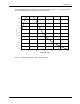
DRAFT Configuring the Camera Inquiry Registers for Video Frame Rate and the Base Address of the Video Mode Command and Status Registers for the Scalable Image Size Format 4-4 Offset Name 200h V_RATE_INQ_0_0 (Format_0, Mode_0) 204h V_RATE_INQ_0_1 (Format_0, Mode_1) 208h V_RATE_INQ_0_2 (Format_0, Mode_2) 20Ch V_RATE_INQ_0_3 (Format_0, Mode_3) 210h V_RATE_INQ_0_4 (Format_0, Mode_4) 214h V_RATE_INQ_0_5 (Format_0, Mode_5) 218h ...
DRAFT Configuring the Camera Inquiry Register for Basic Functions Offset Name 400h BASIC_FUNC_INQ Notes Inquiry Registers for Feature Presence Offset Name 404h Feature_Hi_Inq 408h Feature_Lo_Inq 480h Advanced_Feature_Inq Notes Inquiry Registers for Feature Elements Offset Name 500h BRIGHTNESS_INQ 504h AUTO_EXPOSURE_INQ 508h SHARPNESS_INQ 50Ch WHITE_BAL_INQ 510h HUE_INQ 514h SATURATION_INQ 518h GAMMA_INQ 51Ch SHUTTER_INQ 520h GAIN_INQ 524h IRIS_INQ 528h FOCUS_INQ 52Ch
DRAFT Configuring the Camera Status and Control Registers for the Camera Offset Name Notes 600h CUR_V_FRAME_RATE 604h CUR_V_MODE 608h CUR_V_FORMAT 60Ch ISO_CHANNEL 610h Camera_Power 614h ISO_EN Continuous Shot 618h Memory_Save 61Ch One_Shot / Multi-Shot 620h Mem_Save_Ch Has no effect 624h Cur_Mem_Ch Has no effect Has no effect Has no effect Status and Control Registers for Features Offset Name Notes 800h BRIGHTNESS 804h AUTO_EXPOSURE Has no effect 808h SHARPNESS Has no
DRAFT Configuring the Camera Video Mode Control and Status Registers for Format_7 The base address for each Format_7, Mode_0 camera control register is: Bus_ID, Node_ID, FFFF F1F0 0000 This address is contained in the Format_7 section of the “Inquiry Registers for Video Frame Rate and Base Address of the Video Mode Command and Status Registers for the Scalable Image Size Format.” A register has been prepared for each video mode that is Format_7, Mode_x.
DRAFT Configuring the Camera The base address for each Format_7, Mode_1 camera control register is: Bus_ID, Node_ID, FFFF F1F0 0100 This address is contained in the Format_7 section of the “Inquiry Registers for Video Frame Rate and Base Address of the Video Mode Command and Status Registers for the Scalable Image Size Format.” A register has been prepared for each video mode that is Format_7, Mode_x. The offset field in each of the tables is the byte offset from the above base address.
DRAFT Configuring the Camera The base address for each Format_7, Mode_2 camera control register is: Bus_ID, Node_ID, FFFF F1F0 0200 This address is contained in the Format_7 section of the “Inquiry Registers for Video Frame Rate and Base Address of the Video Mode Command and Status Registers for the Scalable Image Size Format.” A register has been prepared for each video mode that is Format_7, Mode_x. The offset field in each of the tables is the byte offset from the above base address.
DRAFT Configuring the Camera The base address for each Format_7, Mode_3 camera control register is: Bus_ID, Node_ID, FFFF F1F0 0300 This address is contained in the Format_7 section of the “Inquiry Registers for Video Frame Rate and Base Address of the Video Mode Command and Status Registers for the Scalable Image Size Format.” A register has been prepared for each video mode that is Format_7, Mode_x. The offset field in each of the tables is the byte offset from the above base address.
DRAFT Configuring the Camera 4.5 Advanced Features * The advanced features control and status registers are vendor unique and are subject to change. 4.5.1 Advanced Features Access Register The base address for the Advanced Features Access register is: Bus_ID, Node_ID, FFFF F2F0 0000 This address is contained in the Advanced_Feature_Inq register of the “Inquiry register for feature presence” section. The offset field in each of the tables is the byte offset from the above base address.
DRAFT Configuring the Camera Extended Versions Information Register Offset Name Field Bit Description 1014h EXTD_VERSIONS String (Read only) [n Bytes] An ASCII character string that includes the software version numbers for the camera. The length of this string field is equal to the number of quadlets given in the “Length” field of the Inquiry Register for Version Information (see page 4-11).
DRAFT Configuring the Camera Status and Control Register for Test Images This advanced features register can be used to control the operation of the camera’s test image feature (see Section 3.9). Offset 0098h BASLER A101f Name TEST_IMAGE Field Bit Description Presence_Inq (Read only) [0] Presence of this feature 0: N/A 1: Available --- [1..
Configuring the Camera 4-14 DRAFT BASLER A101f
DRAFT Mechanical Considerations 5 Mechanical Considerations 5.1 Camera Dimensions The camera housing for the A101f is manufactured with high precision. Planar, parallel, and angular sides guarantee precise mounting with high repeatability. The A101f camera is equipped with four M4 mounting holes on the front and two M4 mounting holes on each side as indicated in Figure 5-1. ! BASLER A101f Caution! To avoid collecting dust on the sensor, mount a lens on the camera immediately after unpacking it.
Mechanical Considerations DRAFT PHOTO− SENSITIVE SURFACE OF CCD Figure 5-1: A101f Mechanical Dimensions (in mm) 5-2 BASLER A101f
DRAFT Mechanical Considerations 5.2 C-Mount Adapter Dimensions C-Mount Adapter on an A101f C-Mount Adapter PHOTO− SENSITIVE SURFACE OF CCD Figure 5-2: C-Mount Adapter Dimensions (in mm) 5.
DRAFT Mechanical Considerations 5.4 Positioning Accuracy of the Sensor Chip On the A101f, the tolerance for the positioning of the sensor’s image area to the camera housing is ± 0.3 mm in the horizontal and vertical directions. Rotational positioning accuracy is as shown in Figure 5-4. Reference position is the center of the camera housing.
DRAFT Troubleshooting 6 Troubleshooting 6.1 Fault Finding Using Camera LEDs 6.1.1 Yellow LED The A101f regularly performs self tests. Detected errors are signaled by blinking of the yellow LED on the back of the camera. The number of pulses indicate the detected error. If several error states are present, the yellow LED outputs the error codes in succession. See Table 6-1 for the description of the pulses. LED Camera Condition On Continuous The camera is OK.
Troubleshooting 6-2 DRAFT BASLER A101f
DRAFT Revision History Revision History Doc. ID Number Date Changes DA039101 6-Feb.-2001 Initial release. DA039102 18-Apr.-2001 Made numerous small changes to grammar and phrasing. Added connector information in Section 2.1.3. Added ripple specification to Table 1-1 and Section 2.3. Added Section 3.10 containing information on the low smear feature. This feature is available on cameras with FPGA firmware version 2.17 or higher. Version 2.
Revision History ii DRAFT BASLER A101f
DRAFT Index A H advanced features . . . . . . . . . . . . . . . . . . . . . . . 4-11 advanced features access register . . . . . . . . . . 4-11 anti-blooming . . . . . . . . . . . . . . . . . . . . . . . . . . . . 1-2 area of interest . . . . . . . . . . . . . . . . . . . . . . . . . 3-14 housing size . . . . . . . . . . . . . . . . . . . . . . . . . . . . . 1-2 humidity requirements . . . . . . . . . . . . . . . . . . . . . 1-5 B bayer filter . . . . . . . . . . . . . . . . . . . . . . . . . . . . .
DRAFT S sensor anti-blooming . . . . . . . . . . . . . . . . . . . . . . . . pixel size . . . . . . . . . . . . . . . . . . . . . . . . . . . . size . . . . . . . . . . . . . . . . . . . . . . . . . . . . . . . . type . . . . . . . . . . . . . . . . . . . . . . . . . . . . . . . . shock . . . . . . . . . . . . . . . . . . . . . . . . . . . . . . . . . . spectral responsivity color camera . . . . . . . . . . . . . . . . . . . . . . . . . monochrome camera . . . . . . . . . . . . . . . . . .