
User`s manual


Basic Operation & Standard Features
BASLER A102
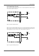
f 3-1
DRAFT
3 Basic Operation and
Standard Features
3.1 Functional Description
3.1.1 Overview
A102f area scan cameras employ a CCD sensor chip which provides features such as a full frame
shutter and electronic exposure time control.
Normally, exposure time and charge readout are controlled by values transmitted to the camera’s
control registers via the IEEE 1394 interface. Control registers are available to set exposure time
and frame rate. There are also control registers available to set the camera for single frame
capture or continuous frame capture.
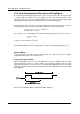
Exposure start can also be controlled via an externally generated trigger (ExTrig) signal. The
ExTrig signal facilitates periodic or non-periodic start of exposure. When exposure start is
controlled by a rising ExTrig signal and the camera is set for the programmable exposure mode,
exposure begins when the trigger signal goes high and continues for a pre-programmed period of
time. Accumulated charges are read out when the programmed exposure time ends.
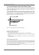
At readout, accumulated charges are transported from the sensor’s light-sensitive elements
(pixels) to the vertical shift registers (see Figure 3-1). The charges from the bottom line of pixels
in the array are then moved into a horizontal shift register. Next, the charges are shifted out of the
horizontal register through an FPGA and into an image buffer. Shifting is clocked according to the
camera’s internal data rate.
As the charges move out of the horizontal shift register, they are converted to voltages which are
proportional to the size of each charge. The voltages are amplified by an internal Variable Gain
Control (VGC) and then digitized by a 12 bit, Analog-to-Digital converter (ADC). For optimal
digitization, gain and brightness can be programmed by setting command registers in the camera.
The data leaves the image buffer and passes back through the FPGA to a 1394 link layer
controller where it is assembled into data packets that comply with the “1394 - based Digital
Camera Specification” (DCAM) issued by the 1394 Trade Association. The packets are passed to
a 1394 physical layer controller which transmits them isochronously to a 1394 interface board in
the host PC. The physical and link layer controllers also handle transmission and receipt of
asynchronous data such as programming commands.