
User`s manual

Configuring the Camera
4-24 BASLER A102
f
DRAFT
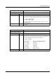
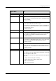
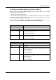
Register Name: Trigger Mode
Offset from Base Address: 0x830
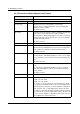
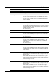
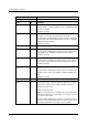
Field Bit Description
Presence Inq 0 Indicates the presence of the trigger mode control feature.
The value will be 1on A102f and A102fc cameras, indicating that trig-
ger mode control is available.
This field is read only.
Abs Control
1 Determines whether the trigger mode will be controlled by the Value
field of this register or by the Absolute Value CSR for the trigger mode.
The value will be 0, indicating that the trigger mode can only be con-
trolled by the Value field of this register. Absolute value control is not
available on A102f and A102fc cameras.
This field is read only.
---
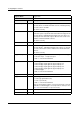
2 ... 5 Reserved
On / Off 6 Sets whether trigger mode control is on or off.
The value will be 1, indicating that trigger mode control is on. The trig-
ger mode control feature can’t be switched off on A102f and A102fc
cameras.
This field is read only.
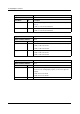
Trigger Polarity 7 Sets the trigger polarity when the camera is using a hardware trigger.
0 = low active input 1 = high active input
Default = 1 on the A102f and A102fc
Trigger Source
8 ... 10 Sets the trigger source.
0 = External trigger signal applied to physical input port 0
1 = External trigger signal applied to physical input port 1
2 = External trigger signal applied to physical input port 2
3 = External trigger signal applied to physical input port 3
7 = Software trigger
Default = 0 on the A102f and A102fc
Trigger Value
11 Not used on the A102f or A102fc. This bit should be ignored.
Trigger Mode 12 ... 15 Sets the trigger mode.
0 = mode 0 (programmable mode)
1 = mode 1 (level mode)
Default = 1 on the A102f and A102fc
When an external trigger signal is used, mode 0 and mode 1 are both
valid. When a software trigger is used, only mode 0 is valid. (See Sec-
tion 3.2 for more information on exposure modes.)
---
16 ... 19 Reserved
Parameter 20 ... 31 Not used on the A102f or A102fc. These bits should be ignored.