
User`s manual

Configuring the Camera
BASLER A102
f 4-27
DRAFT
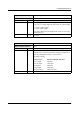
4.4.2.4 Control and Status Registers for Format 7, Mode 0
Format 7, Mode 0 is available on A102f and A102fc cameras. The base address for each Format
7, Mode 0 camera control register is:
Bus ID, Node ID, FFFF F1F0 0000
In each Format 7, Mode 0 register description, an “Offset from the Base Address” is provided. This
is a byte offset from the above base address. The address of a Format 7, Mode 0 register equals
the above base address plus the indicated offset.
Values are stated in decimal format except when marked 0x. Values marked as 0x (e.g., 0x123)
are in hexadecimal format. Bit 0 in each register is the most significant bit.
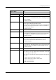
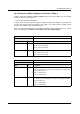
Register Name: Max Image Size Inquiry
Offset from Base Address: 0x000
Field Bit Description
Hmax 0 ... 15 Indicates the maximum horizontal image size in pixels.
Hmax = 1392 on the A102f
Hmax = 1388 on the A102fc
Vmax
16 ... 31 Indicates the maximum vertical image size in pixels.
Vmax = 1040 on the A102f
Vmax = 1038 on the A102fc
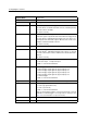
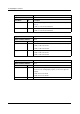
Register Name: Unit Size Inquiry
Offset from Base Address: 0x004
Field Bit Description
Hunit 0 ... 15 Indicates the increment in columns for adjusting the area of interest
width (see Section 3.6). For example, if the Hunit is 2, the width should
be set in increments of 2.
Hunit = 1 on the A102f
Hunit = 2 on the A102fc
Vunit
16 ... 31 Indicates the increment in rows for adjusting the area of interest height
(see Section 3.6). For example, if the Vunit is 1, the height should be
set in increments of 1.
Vunit = 1 on the A102f
Vunit = 2 on the A102fc