
User`s manual


Physical Interface
18 Basler aviator Camera Link
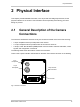
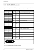
2.2.3 26-Pin MDR Connector
The 26-pin, 0.050” Mini D Ribbon (MDR) female connector is used to transmit video data, control
signals, and configuration commands. The pin assignments and pin numbering for the MDR
connector are as shown in Table 4.
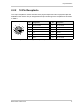
1
Pins 1, 13, 14, and 26 are all tied to ground inside of the camera.
Pin Number Signal Name Direction Level Function
1, 13, 14, 26
1
Gnd Input Ground Ground for the inner shield of the cable
2 X0- Output Camera Link
LVDS
Data from transmitter circuit X
15 X0+
3 X1- Output Camera Link
LVDS
Data from transmitter circuit X
16 X1+
4 X2- Output Camera Link
LVDS
Data from transmitter circuit X
17 X2+
6 X3- Output Camera Link
LVDS
Data from transmitter circuit X
19 X3+
5 XClk- Output Camera Link
LVDS
Pixel clock from transmitter circuit X
18 XClk+
7 SerTC+ Input RS-644
LVDS
Serial communication data receive
(SerTC = "serial to camera")
20 SerTC-
8 SerTFG- Output RS-644
LVDS
Serial communication data transmit
(SerTFG = "serial to frame grabber")
21 SerTFG+
9 CC1- Input RS-644
LVDS
ExTrig (external trigger)
22 CC1+
10 CC2+ Input RS-644
LVDS
Not assigned
23 CC2-
11 None None None None
24 None
12 CC4+ Input RS-644
LVDS
Not assigned
25 CC4-
Table 4: Pin Assignments and Numbering for the 26-pin MDR Connector
1
26
14
13