
User`s manual

Physical Interface
34 Basler aviator Camera Link
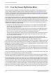
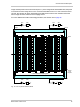
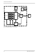
2.10 Camera Link Interface
The Camera Link interface on the aviator is accessed via the 26-pin MDR connector. The Camera
Link interface is designed to be completely compatible with the base Camera Link standard.
The camera has a default Camera Link pixel clock speed of 65 MHz. The pixel clock speed can also
be changed to 32.5 MHz, 40 MHz, or 48 MHz.
The camera can output pixel data in 8 bit, 10 bit, or 12 bit pixel formats and in the 1X2-1Y or 1X-
2YE Camera Link tap geometries.
For more information about changing the Camera Link pixel clock speed, see Section 7.2 on
page 102.
2.10.1 Acquisition Start and Frame Start Trigger Signals
As specified in the Camera Link standard, several camera control channels are built into the
Camera Link interface.These control channels are designated as CC1, CC2, and CC4.
On aviator cameras, the CC1 (camera control 1) channel is assigned by default to be the source
signal for a hardware frame start trigger signal. Camera Link compatible frame grabbers are
typically designed to supply a frame start trigger signal to the camera via CC1 in the Camera Link
interface.
The camera can also be set so that one of these control channels is assigned to be the source
signal for a hardware acquisition start trigger signal.
For more information about setting and using acquisition start and frame start trigger signals, see
Section 5.2 on page 53 and Section 5.3 on page 61.
2.10.2 Camera Link Serial Port Baud Rate
As specified in the Camera Link standard, an RS-644 serial connection must be included on all
Camera Link compliant frame grabbers. Your PC and your camera are able to communicate via this
serial port built into the frame grabber. If you are using Basler’s pylon software to operate the
camera, the serial port is used to communicate pylon commands and replies to and from the
camera. If you are operating the camera via direct register access, the serial port is used to
communicate read and write requests to and from the camera.
If you plan to design your own frame grabber, or if you would like specific details
regarding the way that the Camera LInk interface is implemented on the camera,
refer to the document called Aviator Information for Frame Grabber Designers
(AW000831xx000). You can download the document from the Basler website:
www.baslerweb.com/beitraege/beitrag_en_80604.html.