
User`s manual
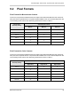


Sensor Bit Depth, Pixel Formats, Tap Geometries, and Clock Speeds
144 Basler ace Camera Link
9.3 Camera Link Tap Geometry
9.3.1 Overview
The Camera Link tap geometry determines how the data that is read out of the imaging sensor will
be transmitted from the camera to the frame grabber in your host PC via the Camera Link interface.
The selection of a camera link tap geometry also determines whether your camera will be operating
in the base, medium, or full Camera Link configuration and which Camera Link connectors on the
camera will be used to transmit pixel data. Table 10 indicates how the Camera Link interface will
operate with each available tap geometry setting.
The X2, X3, X4, X6, X8, or X10 in the tap geometry names indicates the number of Camera Link
taps that will be used for a given configuration (i.e., X2 means 2 taps, X3 means 3 taps, etc.). As a
general rule of thumb, a camera will have a higher maximum allowed frame rate when it is operating
with a tap geometry that uses Camera Link taps.
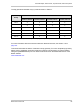
Tap Geometry Setting Camera Link Configuration Camera Link Connectors
Used to Transmit Data
1X2-1Y Base Base Only
1X3-1Y Base Base Only
1X4-1Y Medium Base and Medium/Full
1X6-1Y Medium Base and Medium/Full
1X8-1Y Full Base and Medium/Full
1X10⁻¹Y Full Base and Medium/Full
Table 10: Camera Link Operation at Various Tap Geometry Settings
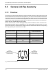
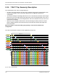
26-pin
SDR Connector
(Base Camera
Link Connection)
Fig. 39: Camera Link Connections
26-pin
SDR Connector
(Medium/Full Camera
Link Connection)