T F A DR Basler racer USER’S MANUAL FOR CAMERA LINK CAMERAS Document Number: AW001185 Version: 01 Language: 000 (English) Release Date: 13 June 2012 Preliminary The information in this document is preliminary and all content is subject to change. Applies to prototype cameras only.
For customers in the U.S.A. This equipment has been tested and found to comply with the limits for a Class A digital device, pursuant to Part 15 of the FCC Rules. These limits are designed to provide reasonable protection against harmful interference when the equipment is operated in a commercial environment. This equipment generates, uses, and can radiate radio frequency energy and, if not installed and used in accordance with the instruction manual, may cause harmful interference to radio communications.
Contacting Basler Support Worldwide Europe: Basler AG An der Strusbek 60 - 62 22926 Ahrensburg Germany Tel.: +49-4102-463-515 Fax.: +49-4102-463-599 bc.support.europe@baslerweb.com Americas: Basler, Inc. 855 Springdale Drive, Suite 203 Exton, PA 19341 U.S.A. Tel.: +1-610-280-0171 Fax.: +1-610-280-7608 bc.support.usa@baslerweb.com Asia: Basler Asia Pte. Ltd. 8 Boon Lay Way # 03 - 03 Tradehub 21 Singapore 609964 Tel.: +65-6425-0472 Fax.: +65-6425-0473 bc.support.asia@baslerweb.com www.baslerweb.
AW00118501000 Table of Contents Table of Contents 1 Specifications, Requirements, and Precautions . . . . . . . . . . . . . . . . . . . . . . . . 1 1.1 Models . . . . . . . . . . . . . . . . . . . . . . . . . . . . . . . . . . . . . . . . . . . . . . . . . . . . . . . . . . . . . . 1 1.2 General Specifications . . . . . . . . . . . . . . . . . . . . . . . . . . . . . . . . . . . . . . . . . . . . . . . . . . 2 1.3 Spectral Response . . . . . . . . . . . . . . . . . . . . . . . . . . . . . . . . . . .
Table of Contents 5.6 AW00118501000 I/O in the Camera Link Interface. . . . . . . . . . . . . . . . . . . . . . . . . . . . . . . . . . . . . . . . . . 5.6.1 Inputs . . . . . . . . . . . . . . . . . . . . . . . . . . . . . . . . . . . . . . . . . . . . . . . . . . . . . . . 5.6.1.1 Input Line Debouncers . . . . . . . . . . . . . . . . . . . . . . . . . . . . . . . . 5.6.1.2 Input Line Inverters . . . . . . . . . . . . . . . . . . . . . . . . . . . . . . . . . . . 5.6.1.
AW00118501000 Table of Contents 8 Features . . . . . . . . . . . . . . . . . . . . . . . . . . . . . . . . . . . . . . . . . . . . . . . . . . . . . . . . 75 8.1 Camera Link Pixel Clock Speed . . . . . . . . . . . . . . . . . . . . . . . . . . . . . . . . . . . . . . . . . . 75 8.2 Gain and Black Level . . . . . . . . . . . . . . . . . . . . . . . . . . . . . . . . . . . . . . . . . . . . . . . . . . 8.2.1 Gain . . . . . . . . . . . . . . . . . . . . . . . . . . . . . . . . . . . . . . . . . . . . . .
Table of Contents iv AW00118501000 Basler racer Camera Link
AW00118501000 Specifications, Requirements, and Precautions 1 Specifications, Requirements, and Precautions This chapter lists the camera models covered by the manual. It provides the general specifications for those models and the basic requirements for using them. This chapter also includes specific precautions that you should keep in mind when using the cameras. We strongly recommend that you read and follow the precautions. 1.
Specifications, Requirements, and Precautions 1.
AW00118501000 1.3 Specifications, Requirements, and Precautions Spectral Response The following graph shows the quantum efficiency curve for monochrome cameras. The quantum efficiency curve excludes lens characteristics and light source characteristics. Quantum Efficiency (e-/Photon) 0.7 0.6 0.5 0.4 0.3 0.2 0.1 0.0 300 400 500 600 700 800 900 1000 1100 Wave Length (nm) Fig.
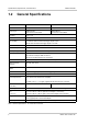
Specifications, Requirements, and Precautions 1.4 1.4.1 AW00118501000 Mechanical Specifications Camera Dimensions and Mounting Points The cameras are manufactured with high precision. Planar, parallel, and angular sides guarantee precise mounting with high repeatability. The camera housings conform to the IP30 protection class provided the camera front or the lens mount is covered by the protective plastic seal that is shipped with the camera.
AW00118501000 Specifications, Requirements, and Precautions 40.07 56 33.77 39.2 6.5 19 49 62 45° 20.99 39.19 51.7 .2 Photosensitive surface of the sensor. For focal flange distances, see the Lens Adapter Dimensions section below. 2 x M4; 6.3 deep 7.51 32.61 ø53 ø47 4 x M4; 6.3 deep 90° 49 4 x M2.5; 3.3 deep 43 Not to Scale Fig.
Specifications, Requirements, and Precautions 1.4.2 AW00118501000 Lens Adapter Dimensions C-mount Adapter C-mount Adapter on a racer 48.57 ø47 < 17.526 Photosensitive Surface of the Sensor ø47 h7 0 -0.025 47.000 46.975 8.5 Not to Scale Fig.
AW00118501000 1.5 Specifications, Requirements, and Precautions Software Licensing Information The software in the camera includes the LWIP TCP/IP implementation. The copyright information for this implementation is as follows: Copyright (c) 2001, 2002 Swedish Institute of Computer Science. All rights reserved. Redistribution and use in source and binary forms, with or without modification, are permitted provided that the following conditions are met: 1.
Specifications, Requirements, and Precautions 1.6 AW00118501000 Avoiding EMI and ESD Problems The cameras are frequently installed in industrial environments. These environments often include devices that generate electromagnetic interference (EMI) and they are prone to electrostatic discharge (ESD). Excessive EMI and ESD can cause problems with your camera such as false triggering or can cause the camera to suddenly stop capturing images.
AW00118501000 Specifications, Requirements, and Precautions 1.7 Environmental Requirements 1.7.1 Temperature and Humidity Housing temperature during operation: 0 °C ... +50 °C (+32 °F ... +122 °F) Humidity during operation: 20 % ... 80 %, relative, non-condensing Storage temperature: -20 °C ... +80 °C (-4 °F ... +176 °F) Storage humidity: 20 % ... 80 %, relative, non-condensing 1.7.
Specifications, Requirements, and Precautions 1.8 AW00118501000 Precautions NOTICE Avoid dust on the sensor. The camera is shipped with a protective plastic seal on the camera front or lens mount. To avoid collecting dust on the camera’s sensor, make sure that you always put the protective seal in place when there is no lens mounted on the camera. Also, make sure to always point the camera downward when there is no protective seal or lens on the camera front or lens mount.
AW00118501000 Specifications, Requirements, and Precautions NOTICE Making or breaking Camera Link connections incorrectly can severely damage the camera. 1. If you supply power to the camera via the Camera Link connection (PoCL), be sure that the power to the camera and to the frame grabber in your PC is switched off before you connect or disconnect the Camera Link cables. 2.
Specifications, Requirements, and Precautions AW00118501000 Warranty Precautions To ensure that your warranty remains in force: Do not remove the camera’s serial number label If the label is removed and the serial number can’t be read from the camera’s registers, the warranty is void. Do not open the camera housing Do not open the housing. Touching internal components may damage them.
AW00118501000 Software and Hardware Installation 2 Software and Hardware Installation The information you will need to do a quick, simple installation of the camera is included in the Installation and Setup Guide for racer Camera Link Cameras (AW001186xx000). You can download the Installation and Setup Guide from the camera’s Downloads section of the Basler website: www.baslerweb.
Software and Hardware Installation 14 AW00118501000 Basler racer Camera Link
AW00118501000 Tools for Changing Camera Parameters 3 Tools for Changing Camera Parameters This chapter provides an overview of the options available for changing the camera’s parameters: The options available with the Basler pylon Driver Package let you change parameters and control the camera by using a stand-alone GUI (known as the pylon Viewer) or by accessing the camera from within your software application using the driver API.
Tools for Changing Camera Parameters 3.1.1 AW00118501000 The pylon Viewer The pylon Viewer is included in Basler’s pylon Driver Package. The Viewer is a standalone application that lets you view and change most of the camera’s parameter settings via a GUI based interface. Using the pylon Viewer software is a very convenient way to get your camera up and running quickly when you are doing your initial camera evaluation or doing a camera design-in for a new project.
AW00118501000 Tools for Changing Camera Parameters version 1.1 or higher. The BBPL adds convenience functions to this API that allow you to read from and write to the registers in Basler Camera Link cameras. The read and write requests are transmitted to the camera via a serial link between the camera and the frame grabber; the serial link is part of the standard Camera Link interface.
Tools for Changing Camera Parameters 18 AW00118501000 Basler racer Camera Link
AW00118501000 Camera Functional Description 4 Camera Functional Description This chapter provides an overview of the camera’s functionality from a system perspective. The overview will aid your understanding when you read the more detailed information included in the later chapters of the user’s manual. Each camera employs a single line CMOS sensor chip designed for monochrome imaging. For 2k cameras, the sensor includes 2048 pixels.
Camera Functional Description AW00118501000 CMOS Sensor Pixels Analog Processing ADCs Digital Processing Digitized Pixel Data; 2 x 12 Bit Fig. 4: CMOS Sensor Architecture for a 2k Sensor or 2k Sensor Segment with 7 µm x 7 µm Pixel Size Camera PC Image Data Sensor Digitized Pixel Data FPGA Image Data Camera Link Interface CC1 CC2 CC3 Frame Grabber CC4 Serial Port Control Control MicroController Control Data Fig.
AW00118501000 Physical Interface 5 Physical Interface This chapter provides detailed information, such as pinouts and voltage requirements, for the physical interface on the camera. This information will be especially useful during your initial design-in process. 5.1 General Description of the Connections The camera is interfaced to external circuity via connectors located on the back of the housing: Two 26-pin, 0.
Physical Interface 5.2 AW00118501000 Camera Connector Pin Assignments and Numbering 5.2.1 6-pin Receptacle The 6-pin receptacle is used to supply power to the camera. The pin assignments and pin numbering for the receptacle are as shown in Table 2.
AW00118501000 Physical Interface Pin Number Signal Name Direction Level Function 1, 26 * Cam Pow. In +12 VDC Camera power, +12 VDC (±10%), < 1% ripple. For more details about PoCL power requirements see the Camera Link specifications v. 2.0 and above. 13, 14 ** Power Ret.
Physical Interface Pin Number AW00118501000 Signal Name Direction Level Function 1, 26 * Cam Pow. In +12 VDC Not used 13, 14 ** Power Ret.
AW00118501000 5.3 5.3.1 Physical Interface Connector Types 6-pin Connector The 6-pin connector on the camera is a Hirose micro receptacle (part number HR10A-7R-6PB) or the equivalent. The recommended mating connector is the Hirose micro plug (part number HR10A-7P-6S) or the equivalent. 5.3.2 26-pin SDR Connectors The 26-pin connectors on the camera are female, 0.03 inch pin spacing, SDR connector as called for in the Camera Link specification.
Physical Interface 5.4 5.4.1 AW00118501000 Cabling Requirements Power Cable A single power cable is used to supply auxiliary power to the camera. The end of the power cable that connects to the camera’s 6-pin connector must be terminated with a Hirose micro plug (part number HR10A-7P-6S) or the equivalent. The cable must be wired as shown in Fig. 7. For proper EMI protection, the power cable terminated with the Hirose connector and attached to the camera must be a twin-cored, shielded cable.
AW00118501000 5.4.2 Physical Interface Camera Link Cables The Camera Link cables must meet the Mini Camera Link cable specifications specified in Appendix D of the Camera Link Standard. Close proximity to strong electromagnetic fields should be avoided. Note: The maximum recommended Camera Link cable length depends on Camera Link clock speed and Camera Link tap geometry.
Physical Interface 5.5 AW00118501000 Camera Power Power can be supplied to the camera in either one of two ways: Via the base Camera Link SDR connector (Power over Camera Link). Via the 6-pin connector (auxiliary power). 5.5.1 Supplying Power Over Camera Link Power can be supplied to the camera via a Camera Link cable as specified in the Camera Link standard v. 2.0 and above. This method of supplying power to the camera is known as Power over Camera Link or PoCL.
AW00118501000 5.5.2 Physical Interface Supplying Auxiliary Power Via the 6-pin Connector Auxiliary power can be supplied to the camera via the 6-pin connector on the back of the camera. Nominal operating voltage is +12 VDC (± 10%) with less than one percent ripple. Power consumption is as shown in the specification tables in Section 1 of this manual. Close proximity to strong magnetic fields should be avoided. See Section 5.2.1 on page 22 for a description of the connector pinouts. See Section 5.4.
Physical Interface 5.5.3 AW00118501000 LED Indicator The LED indicator on the back of the camera signals whether power is present and also provides some basic error indications for the camera. For more information, see Section 8.9 on page 98.
AW00118501000 5.6 5.6.1 Physical Interface I/O in the Camera Link Interface Inputs The camera is equipped with four input lines built into the Camera Link interface. These lines are designated as CC1, CC2, CC3, and CC4 as specified in the Camera Link standard. Typically, input signals are applied to these lines by the frame grabber board attached to the camera. The frame grabber board can typically be configured to supply different types of signals to these inputs as required by the camera user.
Physical Interface AW00118501000 Unfiltered arriving signals Debouncer debouncer value Transferred valid signal delay TIMING CHARTS ARE NOT DRAWN TO SCALE Fig. 8: Filtering of Input Signals by the Debouncer Setting the Debouncer Using Basler pylon The debouncer value is determined by the value of the Line Debouncer Time Abs parameter. The parameter is set in microseconds and can be set in a range from 0 to approximately 1 s.
AW00118501000 Physical Interface Setting the Debouncer Using Direct Register Access To set the value of the input line debouncers via direct register access: For the CC1 line, set the value of the Input Debouncer Time CC1 register as desired (the value represents milliseconds). For the CC2 line, set the value of the Input Debouncer Time CC2 register. For the CC3 line, set the value of the Input Debouncer Time CC3 register.
Physical Interface AW00118501000 Setting an Input Line for Invert Using Direct Register Access To set the invert function on an input line via direct register access: For the CC1 line, set the value of the Line Inverter CC1 register to 0 (false) or 1 (true) as desired. For the CC2 line, set the value of the Line Inverter CC2 register. For the CC3 line, set the value of the Line Inverter CC3 register. For the CC4 line, set the value of the Line Inverter CC4 register.
AW00118501000 5.6.2 Physical Interface Outputs As specified in the Camera Link standard, a "CL Spare" data bit is included in the Camera Link interface. On racer Camera Link cameras, the CL Spare data bit can be used as a camera output line. You can select any one of the camera’s standard output signals to act as the source signal for the CL Spare output line.
Physical Interface 5.6.2.1 AW00118501000 Minimum Output Pulse Width You can use the minimum output pulse width feature to ensure that even very narrow camera output signals will reliably be detected by other devices. The feature allows you to set the output signal to a minimum width. Setting the Minimum Output Pulse Width Using Basler pylon The MinOutPulseWidthAbs parameter sets the CL Spare output signals to a minimum width.
AW00118501000 5.6.2.2 Physical Interface Output Line Inverters You can set the CL Spare output line to invert or not to invert the input signal. Setting the CL Spare Output Line for Invert Using Basler pylon To set the invert function on the CL Spare output line: Use the Line Selector to select CL Spare. Set the value of the Line Inverter parameter to true to enable inversion on the selected line or to false to disable inversion.
Physical Interface AW00118501000 Selecting the Source Signal Using Basler pylon To select one of the camera’s standard output signals as the source signal for the CL Spare output line or to select user output or off: Use the Line Selector to select CL Spare as the output line. Set the value of the Line Source Parameter to Line Trigger Wait, Exposure Active, User Output, or Off. This will select the source signal for the line.
AW00118501000 Physical Interface Selecting the Source Signal Using Direct Register Access To select a camera output signal as the source signal for the CL Spare output line or to designate the line as user settable via direct register access: Set the value of the Line Source CL Spare register to Line Trigger Wait, Exposure Active, or User as desired. For more information about direct register access, see Section 3.2 on page 16.
Physical Interface AW00118501000 For detailed information about using the pylon API, refer to the Basler pylon Programmer’s Guide and API Reference. You can also use the Basler pylon Viewer application to easily set the parameters. Setting the State of a User Output Line Using Direct Register Access To set the state of a user settable output line via direct register access: Set the value of the User Output CL Spare register to 1 (true) or 0 (false) as desired.
AW00118501000 Physical Interface Checking the State of an I/O Line Using Direct Register Access To check the current state of an I/O line via direct register access: For the CC1 line, read the value of the Line Status CC1 register. The value will indicate 1 (true) or 0 (false). For the CC2 line, read the value of the Line Status CC2 register. For the CC3 line, read the value of the Line Status CC3 register. For the CC4 line, read the value of the Line Status CC4 register.
Physical Interface 5.8 AW00118501000 Checking the Line Logic of the I/O Lines Checking the Line Logic Using Basler pylon You can determine the type of line logic for each I/O line using Basler pylon: Use the Line Selector parameter to select a line. Read the value of the Line Logic parameter to determine the type of line logic used by the line. The parameter will indicate whether the logic is positive or negative.
AW00118501000 Acquisition Control 6 Acquisition Control This section provides detailed information about controlling the acquisition of image information. You will find details about triggering line acquisition, about setting the exposure time for acquired lines, about setting the camera’s line acquisition rate, and about how the camera’s maximum allowed line acquisition rate can vary depending on the current camera settings.
Acquisition Control AW00118501000 Exposure Time Control When the trigger mode is set to off, the exposure time for each line acquisition is determined by the value of the camera’s Exposure Time parameter. The minimum and the maximum allowed exposure time for each acquired line are as shown in Table 5. raL204880km raL409680km Min 2.0 µs 2.
AW00118501000 6.1.2 Acquisition Control Line Start with Trigger Mode = On When Trigger Mode is set to on, you must select a source signal for the line start trigger. Trigger Source specifies the source signal. The available selections for Trigger Source are: Software - When the line start trigger source is set to software, the user triggers line start by issuing a TriggerSoftware command to the camera from the host PC.
Acquisition Control AW00118501000 For more information about using a hardware trigger to control line acquisition start, see Section 6.1.5 on page 52. In all cases, the exposure time for each line must be within the minimum and the maximum stated in Table 7 on page 53. This is true regardless of the method used to control exposure.
AW00118501000 Acquisition Control // rate internally. Camera.AcquisitionLineRateEnable.SetValue( true ); Camera.AcquisitionLineRateAbs.SetValue( 60.0 ); You can also use the Basler pylon Viewer application to easily set the parameters. For more information about the pylon API and the pylon Viewer, see Section 3.1 on page 15.
Acquisition Control 6.1.4 AW00118501000 Using a Software Line Start Trigger Signal 6.1.4.1 Introduction If the Line Start Trigger Mode parameter is set to on and the Trigger Source parameter is set to software, you must apply a software line start trigger signal to the camera to begin each line acquisition. Assuming that the camera is in a "waiting for line start trigger" acquisition status, line exposure will start when the software line start trigger signal is received by the camera. Fig.
AW00118501000 Acquisition Control Software Line Start Trigger Signal Received Software Line Start Trigger Signal Received Line Acquisition Exposure Exposure (duration determined by the exposure time parameter or register setting) Fig.
Acquisition Control AW00118501000 // Set for the timed exposure mode Camera.ExposureMode.SetValue( ExposureMode_Timed ); // Set the exposure time Camera.ExposureTimeAbs.SetValue( 300 ); while ( ! finished ) { // Execute a trigger software command to apply a line start // trigger signal to the camera Camera.TriggerSoftware.
AW00118501000 Acquisition Control Setting the Parameters and Applying the Signal Using Direct Register Access To set the parameters needed to perform software line start triggering via direct register access: Set the value of the Acquisition Line Period Enable register to 0 (false). (This will disable the camera’s ability to internally control the line period and allow you to control the line rate with software trigger signals.) Set the value of the Trigger Mode Line Start register to On.
Acquisition Control 6.1.5 6.1.5.1 AW00118501000 Using a Hardware Line Start Trigger Signal Introduction If the Trigger Mode parameter for the line start trigger is set to on and the Trigger Source parameter is set to CC1, CC2, CC3, or CC4, an externally generated electrical signal injected into the selected source will act as the line start trigger signal for the camera.
AW00118501000 Acquisition Control For more information about determining the maximum allowed line rate with the current camera settings, see Section 6.4 on page 66. For more information about setting the camera for hardware triggering and selecting the source to receive the ExLSTrig signal, see Section 6.1.5 on page 52. For more information about CC1, CC2, CC3, and CC4, see Section 5.6.1 on page 31. 6.1.5.
Acquisition Control AW00118501000 If the camera is set for rising edge triggering, the exposure time starts when the ExLSTrig signal rises. If the camera is set for falling edge triggering, the exposure time starts when the ExLSTrig signal falls. Fig. 11 illustrates timed exposure with the camera set for rising edge triggering. ExLSTrig Signal Period ExLSTrig Signal Exposure (duration determined by the exposure time parameter or register setting) Fig.
AW00118501000 Acquisition Control Trigger Width Exposure Mode When trigger width exposure mode is selected, the length of the exposure for each line acquisition will be directly controlled by the ExLSTrig signal. If the camera is set for rising edge triggering, the exposure time begins when the ExLSTrig signal rises and continues until the ExLSTrig signal falls.
Acquisition Control AW00118501000 You should set Exposure Overlap Time Max to represent the shortest exposure time you intend to use. For example, assume that you will be using trigger width exposure mode and that you intend to use the ExLSTrig signal to vary the exposure time in a range from 3000 µs to 5500 µs. In this case you would set the camera’s Exposure Overlap Time Max to 3000 µs. For more information about the Line Trigger Wait signal, see Section 6.3.3 on page 64 6.1.5.
AW00118501000 Acquisition Control // Set the mode for the selected trigger Camera.TriggerMode.SetValue( TriggerMode_On ); // Set the source for the selected trigger to CC1 Camera.TriggerSource.SetValue ( TriggerSource_CC1 ); // Set the trigger activation mode to rising edge Camera.TriggerActivation.SetValue( TriggerActivation_RisingEdge ); // Set for the trigger width exposure mode Camera.ExposureMode.
Acquisition Control AW00118501000 Exposure Start and Exposure End Delays When the line start trigger mode is set to on and an input line is selected as the source signal for the line start trigger, there is a delay between the transition of the line start signal and the actual start of exposure. For example, if you are using the timed exposure mode with rising edge triggering, there is a delay between the rise of the signal and the actual start of exposure. There is also an exposure end delay, i.e.
AW00118501000 Acquisition Control 6.2 Frequency Converter The camera is equipped with a frequency converter module that allows triggering the camera at a frequency that differs from the frequency of the input signals received. The frequency converter module includes three sub-modules acting in sequence on the original signals: The pre-divider module receives the input signals.
Acquisition Control AW00118501000 module is passed out from the divider module and, accordingly, the frequency is halved. If a post-divider of 1 is selected every signal received from the multiplier module is passed out unchanged from the divider module. You can use the frequency converter to multiply the original signal frequency by a fractional value.
AW00118501000 Acquisition Control Set the desired frequency value of the Frequency Converter Multiplier register. Set the desired frequency value of the Frequency Converter Post Divider register. For more information about direct register access, see Section 3.2 on page 16.
Acquisition Control AW00118501000 6.3 Acquisition Monitoring Tools The camera includes the acquisition status feature and generates these output signals that you can use to monitor the progress of line acquisition by the camera: the exposure active signal the line trigger wait signal. The camera also allows selecting the output of the frequency converter module as output signals. In addition, you can check the camera’s acquisition status (see below). 6.3.
AW00118501000 Acquisition Control You can also use the Basler pylon Viewer application to easily set the parameters. Selecting the Exposure Active Signal as the Source Signal for the CLSpare Output Line Using Direct Register Access You can select the exposure active signal as the source signal for the camera’s CL Spare output line.
Acquisition Control AW00118501000 // Check the line start trigger acquisition status // Set the acquisition status selector Camera.AcquisitionStatusSelector.SetValue ( AcquisitionStatusSelector_LineTriggerWait ); // Read the acquisition status bool IsWaitingForLineTrigger = Camera.AcquisitionStatus.GetValue(); You can also use the Basler pylon Viewer application to easily set the parameters. For more information about the pylon API and the pylon Viewer, see Section 3.1 on page 15.
AW00118501000 Acquisition Control You can also use the Basler pylon Viewer application to easily set the parameters. For more information about the pylon API and the pylon Viewer, see Section 3.1.1 on page 16.
Acquisition Control 6.4 AW00118501000 Maximum Allowed Line Acquisition Rate The maximum allowed line acquisition rate for your camera is not static. It can vary depending on how certain camera features are set. In general, the following factors can affect the maximum allowed line rate: The Camera Link pixel clock speed and the Camera Link tap geometry settings.
AW00118501000 Acquisition Control Using Basler pylon to Check the Maximum Allowed Line Rate You can use the Basler pylon API to read the current value of the Resulting Line Rate Abs parameter from within your application software using the Basler pylon API. The following code snippet illustrates using the API to get the parameter value: // Get the resulting line rate double resultingLps = Camera.ResultingLineRateAbs.
Acquisition Control 6.4.1 AW00118501000 Increasing the Maximum Allowed Line Rate You may find that you would like to acquire lines at a rate higher than the maximum allowed with the camera’s current settings. In this case, you must first determine what factor is most restricting the maximum line rate. The descriptions of the three factors that appear below will let you determine which factor is restricting the rate. Factor 1: Factor 1 is the sensor readout time.
AW00118501000 Acquisition Control Where: CL Clk is the Camera Link clock speed for your camera model (see Section 8.1 on page 75 Taps is the number of Camera Link taps being used as determined by the current Camera Link tap geometry setting (see Section 7.2 on page 73) AOI Width is the width of the AOI based on the current AOI width setting (see Section 8.
Acquisition Control 70 AW00118501000 Basler racer Camera Link
AW00118501000 Pixel Formats and Tap Geometries 7 Pixel Formats and Tap Geometries This chapter provides information about the sensor bit depths, pixel formats, and pixel clock speeds available on the camera. For a description of tap geometries and complete details regarding the way that pixel data is handled by the camera, refer to the Basler document named racer Camera Link Information for Frame Grabber Designers (AW001187xx000).
Pixel Formats and Tap Geometries AW00118501000 Pixel Format Interaction with the Sensor Bit Depth The camera’s sensor can capture image data at 12 bit depth. There is an interaction between the Sensor Bit Depth setting and the Pixel Format setting as described in Table 11.
AW00118501000 7.2 Pixel Formats and Tap Geometries Camera Link Tap Geometry The Camera Link tap geometry determines how the data that is read out of the imaging sensor will be transmitted from the camera to the frame grabber in your host PC via the Camera Link interface. The selection of a camera link tap geometry also determines whether your camera will be operating in the base, medium, or full Camera Link configuration and which Camera Link connectors on the camera will be used to transmit pixel data.
Pixel Formats and Tap Geometries 7.2.1 AW00118501000 Setting the Tap Geometry Setting the Tap Geometry Using Basler pylon You can use the pylon API to set the Camera Link tap geometry from within your application software. The following code snippet illustrates using the API to set the tap geometry: // Set the tap geometry to 1X2 Camera.ClTapGeometry.SetValue( ClTapGeometry_Geometry1X2 ); // Set the tap geometry to 1X4 Camera.ClTapGeometry.
AW00118501000 Features 8 Features This chapter provides detailed information about the features available on each camera. It also includes an explanation of their operation and the parameters associated with each feature. 8.1 Camera Link Pixel Clock Speed The camera features selectable Camera Link pixel clock speeds. The pixel clock speed determines the rate at which pixel data will be transmitted from the camera to the frame grabber in your PC via the Camera Link interface.
Features AW00118501000 Camera.ClPixelClock.SetValue( ClPixelClock_PixelClock48 ); You can use the pylon API to set the pixel clock speed to 32.5, 48, 65, or 83.5 MHz. These are the only valid values for the pixel clock speed. If you attempt to use the API to set the clock speed to a value other then these, the camera will automatically round the setting down to the nearest valid speed. You can also use the Basler pylon Viewer application to easily set the parameters.
AW00118501000 Features 8.2 Gain and Black Level 8.2.1 Gain The camera’s gain is adjustable. As shown in Fig. 16, increasing the gain increases the slope of the response curve for the camera. This results in an increase in the gray values output from the camera for a given amount of output from the imaging sensor. Decreasing the gain decreases the slope of the response curve and results in lower gray values for a given amount of sensor output.
Features 8.2.1.1 AW00118501000 Analog Gain The camera’s analog gain is determined by the Gain parameter with the gain selector set to Analog All. All pixels in the sensor are affected by this setting. The allowed parameter values are 1 and 4. A parameter value of 1 corresponds to 0 dB and gain will not be modified. A parameter value of 4 corresponds to 12 dB and an amplification factor of 4.
AW00118501000 8.2.1.2 Features Digital Gain Adjusting the camera’s digital gain will digitally shift the group of bits that is output for the pixel values from each ADC in the camera. Increasing the digital gain parameter value will result in an amplified gain and therefore in higher pixel values. Decreasing the digital gain setting will result in a decreased gain and therefore in lower pixel values. The digital gain parameter values can be set on an integer scale ranging from 256 to 2047.
Features AW00118501000 You can set the Gain Selector and the Gain parameter value from within your application software by using the pylon API. The following code snippet illustrates using the API to set the selector and the parameter value: // Set Gain Digital All Camera.GainSelector.SetValue( GainSelector_All ); Camera.GainRaw.SetValue( 256 ); For detailed information about using the pylon API, refer to the Basler pylon Programmer’s Guide and API Reference.
AW00118501000 8.2.2 Features Black Level Adjusting the camera’s black level will result in an offset to the pixel values output from the camera. The camera’s black level is determined by the Black Level Raw parameter with the black Level selector set to All. All pixels in the sensor are affected by this setting. If the camera is set for a pixel data format with an 8 bit depth, an increase of 16 in a black level setting will result in a positive offset of 1 in the pixel values output from the camera.
Features 8.3 AW00118501000 Remove Parameter Limits For each camera feature, the allowed range of any associated parameter values is normally limited. The factory limits are designed to ensure optimum camera operation and, in particular, good image quality. For special camera uses, however, it may be helpful to set parameter values outside of the factory limits. The remove parameter limits feature lets you remove the factory limits for parameters associated with certain camera features.
AW00118501000 8.4 Features Image Area of Interest (AOI) The image area of interest feature lets you specify a portion of the sensor line. During operation, only the pixel information from the specified portion of the line is read out of the sensor and transmitted from the camera to the frame grabber. One of the main advantages of the AOI feature is that decreasing the size of the AOI can increase the camera’s maximum allowed acquisition line rate.
Features AW00118501000 Camera Link Tap Geometry Offset X Increment Width Increment 1X2 8 8 1X4 8 8 1X8 8 8 1X10 8 40 Table 13: Camera Link Tap Geometry and Related Increments for AOI Offset X and Width For example, if you are working with a camera that has a sensor with 2048 pixels and if you have selected the 1X4 Camera Link tap geometry: Offset X + AOI Width 2048 The AOI offset X can be set to 0, 8, 16, 24, etc. The AOI width can be set to 8, 16, 24, 32, etc.
AW00118501000 Features Setting the Image AOI Using Direct Register Access To set the AOI Offset X and Width parameter values via direct register access: Set the value of the Offset X register. Set the value of the Width register. Using the Image AOI Feature with Horizontal Binning Enabled If the camera’s horizontal binning feature (see Section 8.6 on page 89) is enabled, it will have an effect on the way that you set up the area of interest.
Features AW00118501000 8.5 Luminance Lookup Table The type of electronics used on the camera allow the camera’s sensor to acquire pixel values at a 12 bit depth. Normally, when a camera is set for a 12 bit pixel data format, the camera uses the actual 12 bit pixel values reported by the sensor. The luminance lookup table feature lets you create a custom 12 bit to 12 bit lookup table that maps the actual 12 bit values output from the sensor to substitute 12 bit values of your choice.
AW00118501000 Features 4095 Substitute 12 Bit Value 3072 2048 1024 0 0 1024 2048 3072 4095 Actual 12 Bit Sensor Value Fig. 18: Lookup Table with Values Mapped in a Linear Fashion 4095 Substitute 12 Bit Value 3072 2048 1024 0 0 1024 2048 3072 4095 Actual 12 Bit Sensor Value Fig.
Features AW00118501000 Changing the Values in the Luminance Lookup Table and Enabling the Table Using Basler pylon You can change the values in the luminance lookup table (LUT) and enable the use of the lookup table by doing the following: 1. Use the LUT Selector to select a lookup table. (Currently there is only one lookup table available, i.e., the "luminance" lookup table described above.) 2. Use the LUT Index parameter to select an index number. 3.
AW00118501000 8.6 Features Binning Binning increases the camera’s response to light by summing the charges from adjacent pixels into one pixel. With horizontal binning, the charges of 2, 3, or a maximum of 4 adjacent pixels are summed and are reported out of the camera as a single pixel. Fig. 20 illustrates horizontal binning. Horizontal Binning by 2 Horizontal Binning by 3 Horizontal Binning by 4 Fig.
Features AW00118501000 8.7 Gamma Correction The gamma correction feature lets you modify the brightness of the pixel values output by the camera’s sensor to account for a non-linearity in the human perception of brightness.
AW00118501000 Features Enabling Gamma Correction and Setting the Gamma Using Direct Register Access To enable gamma correction and to set the gamma value via direct register access: Set the value of the Gamma Enable register to Enabled. Set the value of the Gamma Selector register to User. If the Gamma Selector is set to User, set the value in the Gamma register to the desired gamma value. For more information about direct register access, see Section 3.2 on page 16.
Features AW00118501000 8.8 Shading Correction Two types of shading correction are available on the camera, offset shading correction and gain shading correction. You can set the camera to only perform offset shading correction, to only perform gain shading correction, or to perform both types of shading correction. 8.8.
AW00118501000 8.8.3 Features Default Shading Set File and User Shading Set File For each type of shading correction, two types of shading set files are available in the camera’s nonvolatile memory: The first type of shading set file is called the "defaultshading" file. One "defaultshading" file is available for offset shading correction and another one for gain shading correction.
Features AW00118501000 Creating a "Usershading" File for Offset Shading Correction Creating a "usershading" file for offset shading correction will overwrite any "usershading" file for offset shading correction that is already in the camera’s memory. If you want to preserve the previous "usershading" file save it to your PC before creating the new "usershading" file. For information about saving a "usershading" file to the PC, see Section 8.8.3.2 on page 96.
AW00118501000 Features Creating a "Usershading" File for Gain Shading Correction Creating a "usershading" file for gain shading correction will overwrite any "usershading" file for gain shading correction that is already in the camera’s memory. If you want to preserve the previous "usershading" file save it to your PC before creating the new "usershading" file. For information about saving a "usershading" file to the PC, see Section 8.8.3.2 on page 96.
Features AW00118501000 For more information about the line start trigger mode, see Section 6.1 on page 43. After 128 line acquisitions are completed the camera creates the "usershading" file automatically. The "usershading" file is stored in the camera’s non-volatile memory and is not lost if the camera power is switched off. Any time you make a change to the optics or lighting or if you change the camera’s gain settings or exposure mode, you must create a new "usershading" file.
AW00118501000 8.8.3.3 Features Working with Shading Sets Using Direct Register Access Once you have created shading set files, you can use the following registers to work with the shading sets: Offset Shading Enable/Gain Shading Enable - is used to enable and disable offset or gain shading correction. Offset Shading Set Selector/Gain Shading Set Selector - is used to select the shading set to which the activate and the create commands will be applied.
Features 8.9 AW00118501000 Error Detection 8.9.1 LED Indicator The LED indicator on the back of the camera includes both a small red LED and a small green LED. The LED indicator signals the camera’s current condition as shown in Table 14. LED State Status Indication Red and Green Both Off No power to the camera Continuous Green The camera has booted up successfully and is OK. Flashing Green The camera is set to expect an external trigger signal on an input, but no trigger signal is present.
AW00118501000 8.9.2 Features Error Codes The camera can detect several user correctable errors. If one of these errors is present, the camera will set an error code and will flash alternately both the red and green LEDs in the LED indicator. The following table indicates the available error codes: Code Condition Meaning 0 No Error The camera has not detected any errors since the last time that the error memory was cleared. 1 Overtrigger An overtrigger has occurred.
Features AW00118501000 Reading and Clearing the Error Codes Using Basler pylon You can use the pylon API to read the value of the Last Error parameter and to execute a Clear Last Error command from within your application software. The following code snippets illustrate using the API to read the parameter value and execute the command: // Read the value of the last error code in the memory LastErrorEnums lasterror = Camera.LastError.
AW00118501000 Features 8.10 Test Images All cameras include the ability to generate test images. Test images are used to check the camera’s basic functionality and its ability to transmit an image to the host PC. Test images can be used for service purposes and for failure diagnostics. When the camera is in test image mode, the optics and the imaging sensor are not used. The lines that make up each test image are generated internally by the camera’s logic and are transmitted to the host PC line by line.
Features AW00118501000 Enabling a Test Image Using Direct Register Access To enable a test image via direct register access: Set the value of the Test Image Selector register to Test Image 1, 2, 3, 4, or 5 as desired. To disable test images: Set the value of the Test image Selector Register to Off. For more information about direct register access, see Section 3.2 on page 16. 8.10.
AW00118501000 Features Test Image 3 - Moving Diagonal Gray Gradient (12 bit) The 12 bit moving diagonal gray gradient test image is similar to test image 2, but it is a 12 bit pattern. The image moves by one pixel from right to left whenever a new line acquisition is initiated. The test pattern uses a counter that increments by one for each new line acquisition.
Features AW00118501000 8.11 Device Information Parameters Each camera includes a set of "device information" parameters. These parameters provide some basic information about the camera. The device information parameters include: Device Vendor Name (read only) - contains the name of the camera’s vendor. This string will always indicate Basler as the vendor. Device Model Name (read only) - contains the model name of the camera, for example, raL2048-80km.
AW00118501000 Features // Read the Firmware Version parameter Pylon::String_t firmwareVersion = Camera.DeviceFirmwareVersion.GetValue(); // Read the Device ID parameter Pylon::String_t deviceID = Camera.DeviceID.GetValue(); // Write and read the Device User ID Camera.DeviceUserID = "custom name"; Pylon::String_t deviceUserID = Camera.DeviceUserID.GetValue(); // Read the Sensor Width parameter int64_t sensorWidth = Camera.SensorWidth.
Features AW00118501000 Working with Device Information Parameters Using Direct Register Access When working with the camera via direct register access, you can do the following: Register Name Read the Value Device Vendor Name Device Model Name Device Manufacturer Info Device Version Device Firmware Version Device ID Device User ID Device Scan Type Sensor Width Sensor Height Width Max Height Max Write the Value Table 16: Working with Registers Related
AW00118501000 Features 8.12 User Defined Values The camera can store two "user defined values". These two values are 32 bit signed integer values that you can set and read as desired. They simply serve as convenient storage locations for the camera user and have no impact on the operation of the camera. The two values are designated as Value 1 and Value 2.
Features AW00118501000 8.13 Configuration Sets A configuration set is a group of values that contains all of the parameter settings needed to control the camera. There are three basic types of configuration sets: the active configuration set, the default configuration set, and user configuration sets. Active Configuration Set The active configuration set contains the camera’s current parameter settings and thus determines the camera’s performance, that is, what your image currently looks like. When Fig.
AW00118501000 Features Default Startup Set You can select the default configuration set or one of the user configuration sets stored in the camera’s non-volatile memory to be the "default startup set." The configuration set that you designate as the default startup set will be loaded into the active set whenever the camera starts up at power on or after a reset. Instructions for selecting the default startup set appear in Section 8.13.3 on page 111. 8.13.
Features AW00118501000 8.13.2 Loading a Saved Set or the Default Set into the Active Set If you have saved a configuration set into the camera’s non-volatile memory, you can load the saved set from the camera’s non-volatile memory into the camera’s active set. When you do this, the loaded set overwrites the parameters in the active set. Since the settings in the active set control the current operation of the camera, the settings from the loaded set will now be controlling the camera.
AW00118501000 Features 8.13.3 Selecting the Default Startup Set You can select the default configuration set or one of the user configuration sets stored in the camera’s non-volatile memory to be the "default startup set". The configuration set that you designate as the default startup set will be loaded into the active set whenever the camera starts up at power on or after a reset.
Features 112 AW00118501000 Basler racer Camera Link
AW00118501000 Troubleshooting and Support 9 Troubleshooting and Support This chapter outlines the resources available to you if you need help working with your camera. 9.1 Tech Support Resources If you need advice about your camera or if you need assistance troubleshooting a problem with your camera, you can contact the Basler technical support team for your area. Basler technical support contact information is located in the front pages of this manual.
Troubleshooting and Support AW00118501000 9.3 Before Contacting Basler Technical Support To help you as quickly and efficiently as possible when you have a problem with a Basler camera, it is important that you collect several pieces of information before you contact Basler technical support. Copy the form that appears on the next two pages, fill it out, and fax the pages to your local dealer or to your nearest Basler support center.
AW00118501000 7 How often did/does the problem occur? Troubleshooting and Support Once. Every time. Regularly when: Occasionally when: 8 How severe is the problem? Camera can still be used. Camera can be used after I take this action: Camera can no longer be used. 9 10 Did your application ever run without problems? Yes No Parameter set It is very important for Basler technical support to get a copy of the exact camera parameters that you were using when the problem occurred.
Troubleshooting and Support 116 AW00118501000 Basler racer Camera Link
AW00118501000 Revision History Revision History Doc. ID Number Date Changes AW00118501000 13 June 2012 Preliminary release of this document. Applies to prototype cameras only.
Revision History 118 AW00118501000 Basler racer Camera Link
AW00118501000 Index Index A acquisition status indicator .......................63 acquisition status parameter ..............63, 64 analog gain...............................................78 AOI see area of interest API, pylon .................................................16 B Basler binary protocol library....................16 binary protocol library ...............................16 binning......................................................89 black level mono cameras .........................
Index AW00118501000 G M gain analog ................................................78 digital..................................................79 mono cameras ...................................77 gain shading correction ............................92 gamma correction ....................................90 max height parameter ............................ 104 max width parameter ............................. 104 maximum allowed frame rate ...................66 maximum exposure time ..............
AW00118501000 Index R U registers....................................................16 remove limits parameter...........................82 removing parameter limits ........................82 return material authorization...................113 RMA number ..........................................113 user defined values ................................107 user output value parameter ....................39 user settable output lines ...................38, 39 user shading set file ......................
Index 122 AW00118501000 Basler racer Camera Link