
Install Instructions
Installation Instructions
Issue Date September 17, 2008
© 2008 BASO Gas Products 1
Part No. BASO-INS-G92, Rev. A www.baso.com
G92 Series BASOTROL® Automatic Pilot Gas Valve
Installation
IMPORTANT: Only qualified personnel should
install or service BASO® Gas Products. These
instructions are a guide for such personnel. Carefully
follow all instructions in this document and all
instructions for the appliance.
IMPORTANT: Make all gas installations in
accordance with applicable local, national, and
regional regulations.
!
WARNING: Risk of Explosion or Fire.
Shut off the gas supply at the main manual shutoff
valve before installing or servicing the G92. Failure
to shut off the gas supply can result in the release of
gas during installation or servicing, which can lead to
an explosion or fire, and may result in severe
personal injury or death.
!
CAUTION: Risk of Electrical Shock.
Disconnect power supply before making electrical
connections to avoid electrical shock.
IMPORTANT: Verify that the valve is installed
only in applications where the specified maximum
ambient (surface) temperature and maximum
operating pressures will not exceed the limits in the
Technical Specifications section.
To install the G92 valve:
1. Shut off the gas at the main manual shutoff valve.
2. Compare the voltage on the valve with the power
source voltage to ensure the correct unit is being
installed. For valves with 25 volt coils, use a
National Electrical Code (NEC) Class 2
transformer.
Note: The transformer must be mounted to a
grounded metal enclosure.
3. Ensure that the gas flows through the valve body
in the direction indicated by the arrow on the valve
body when installing the valve on the manifold. If
the valve is installed with the gas flow in the
opposite direction of the arrow, leakage can occur.
IMPORTANT: Do not use a wrench on any
surface other than the casting flats provided at the
inlet and outlet ends of the valve body. The G92 may
be damaged in the mounting process if a wrench is
used on any other surface. Using a wrench
incorrectly may void the warranty.
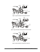
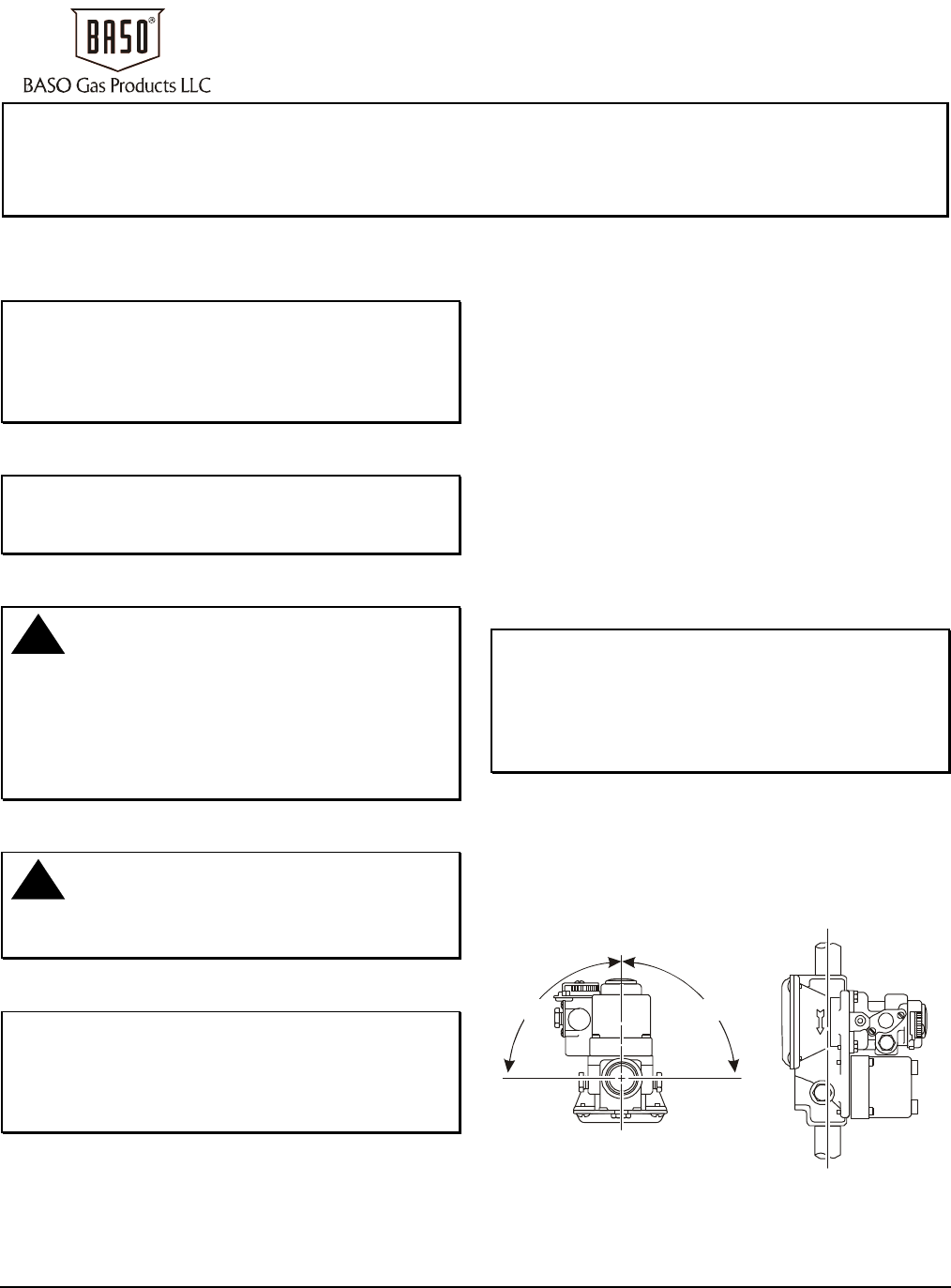
4. Mount the G92 valve on a horizontal manifold with
the magnetic operator point up (vertical) or in a
position not exceeding 90° from vertical. The valve
may also be mounted on a vertical manifold in any
position around its axis (see Figure 1).
Vertical mounting may be 360º
around its axis with the gas flow
either up or down, but always in
the direction of the arrow.
Horizontal mounting limited
to 90º from upright.
90º 90º
Figure 1: G92 Mounting Positions