
Install Instructions
4 G92 Series BASOTROL Automatic Pilot Gas Valve Installation Instructions
Setup and Adjustments
Checkout
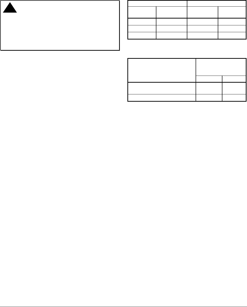
!
WARNING: Risk of Explosion or Fire.
Follow this or an equivalent checkout procedure
after installation. Before leaving the installation,
verify that the gas valve functions properly and that
the system has no gas leaks. Gas leaks can lead to
an explosion or fire, and may result in severe
personal injury or death.
Make sure all components are functioning properly by
performing the following test:
1. Open all upstream shutoff valves and test all joints
and connections for leaks with a soap solution.
2. Close the main upstream manual shutoff valve
and the B valve (applications with a B valve only)
and wait at least five minutes for unburned gas to
escape from the appliance. Then reopen the
valves.
3. Push the reset button and light the pilot burner.
Continue to hold the reset button for 30 to
45 seconds or until the pilot remains burning when
the reset button is released.
4. Set the thermostat to the highest setting. The main
burner should now ignite from the pilot burner.
5. Extinguish the burner by closing the main
upstream manual shutoff valve. Verify that the
valve drops out within 90 seconds.
6. Relight the pilot burner.
7. Check the millivoltage (mV) output of the
thermocouple and the milliampere (mA) dropout
range of the BASO power unit to ensure that they
meet the values listed in and Table 2. Step-by-
step procedures for these checks are included
with the Y99AB-4 BASO Test Kit Application Note.
8. Observe at least three complete operating cycles
to make sure that all components are functioning
properly.
9. Reset the thermostat to the desired setting before
leaving the installation.
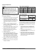
Table 1: Thermocouple Output
Thermocouple mV Range
Lead
Type
Turn
Down
Normal
Not Less
Than
K15
4 mV 20-28 15
K16
4 mV 25-35 17
K19
4 mV 25-35 17
Table 2: Dropout Range
mA Range of
Power Unit
Assembly
Series Number
Low High
All models except G92CAA-19
and G92CBA-10
100 300
G92CAA-19 and G92CBA-10
100 200
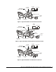
Pilot Gas Adjustment (Applications with a B Valve)
Models with an optional manual rotor pilot valve allow
for the adjustment of the pilot gas flame. To adjust the
pilot gas flame:
1. Loosen the round-head screw holding the small
adjustment plate beside the manual rotor pilot
valve knob, and turn the knob clockwise as far as
it goes.
2. Slowly push the adjustment plate in a
counterclockwise direction while watching the size
of the pilot burner flame.
3. Stop moving the adjustment plate when the pilot
flame reaches the proper size, and tighten the
round-head screw. The rotor pilot valve provides
complete On/Off operation with the adjustment
fixed at the On position.