
Manual


Installation Instructions BGA Series
Issue Date August 18, 2011
© 2011 BASO Gas Products 1
Part No. BASO-INS-BGA158_171_110, Rev. B www.baso.com
BGA158, BGA171 and BGA110 Series
Shutoff Gas Valve
Applications
The BGA Series shutoff gas valve is an electrically
operated gas valve that automatically open and close
on a demand signal from a thermostat or other
controlling device. Typical applications include
heaters, wall furnaces, commercial cooking
equipment, roof top makeup units and similar
applications. The BGA Series can be used with natural
gas and LP gas at pressures up to 0.5 psi. Its compact
size permits installation in space restrictive
applications.
Installation
IMPORTANT: Only qualified personnel should
install or service BASO® Gas Products. These
instructions are a guide for such personnel. Carefully
follow all instructions in this document and all
instructions for the appliance.
IMPORTANT: Make all gas installations in
accordance with applicable local, national, and
regional regulations.
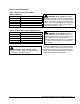
!
CAUTION: Risk of Electric Shock.
Disconnect power supply before making electrical
connections to avoid electric shock.
!
WARNING: Risk of Explosion or Fire.
Shut off the gas supply at the main manual shutoff
valve before installing or servicing the BGA Series.
Failure to shut off the gas supply can result in the
release of gas during installation or servicing, which
can lead to an explosion or fire, and may result in
severe personal injury or death.
!
WARNING: Risk of Explosion, Fire, or
Electric Shock. Label all wires before they are
disconnected when replacing or servicing the
BGA Series. Wiring errors can cause improper or
dangerous operation and may result in an explosion,
fire, or electric shock leading to severe personal
injury or death.
IMPORTANT: Verify that the valve is installed
only in applications where the specified maximum
ambient (surface) temperature and maximum
operating pressure does not exceed the limits in the
Technical Specifications section.
To install the BGA Series valve:
1. Shut off power to the appliance.
2. Shut off the gas at the main manual shutoff valve.
3. Label each wire with the correct terminal
designation prior to disconnection.
4. Compare the voltage on the valve with the power
source voltage to ensure the correct unit is being
installed. For valves with 25-volt coils, use a
National Electrical Code (NEC), Class 2
transformer.
Note: The transformer must be mounted to a
grounded metal enclosure.
5. Ensure that the gas flows through the valve body
in the direction indicated by the “IN” and “OUT” or
by the arrow on the valve body. If the valve is
installed with the gas flow in the opposite
direction, leakage can occur.
IMPORTANT: Do not use a wrench on any
surface other than the casting flats provided at the
inlet and outlet ends of the valve body.
The BGA Series may be damaged in the mounting
process if a wrench is used on any other surface.
Using a wrench incorrectly may void the warranty.