
Owner's manual

Installation Instructions G960
Issue Date October 4, 2011
© 2011 BASO Gas Products
1
Part No. BASO-INS-G960 Rev. E www.baso.com
G960 Series Multi-Functional Gas Control Valve
Installation
IMPORTANT: These instructions are intended as a
guide for qualified personnel installing or servicing
BASO® Gas Products products. Carefully follow all
instructions in this bulletin and all instructions on the
appliance. Limit repairs, adjustments, and servicing
to the operations listed in this bulletin or on the
appliance.
!
WARNING: Risk of Fire or Explosion.
The system must meet all applicable local, national,
and regional regulations. Improper installation may
cause gas leaks, explosions, property damge, and
injuries.
!
WARNING: Risk of Fire or Explosion.
To prevent leakage of upstream gas, shut off the gas
supply at the main manual shutoff valve before
installing or servicing the G960 valve.
Mounting
!
CAUTION: Risk of Equipment Damage.
To prevent damage to the valve when mounting to
pipework, do not use a wrench on any surface other
than the casting flats provided at the inlet and outlet
ends of the valve body.
To install the G960 valve:
1. Ensure that the specified maximum ambient
(surface) temperature is not exceeded (see the
Technical Data section).
2. Ensure that the power supply voltage is
compatible with the required control valve voltage.
3. When installing the valve on the manifold, ensure
that the gas flows through the valve body in the
direction indicated by the arrow on the valve body.
If the valve is installed with the gas flow in the
opposite direction of the arrow, leakage can occur.
4. Shut off the gas at the main manual shutoff valve.
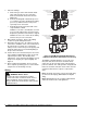
5. Mount the valve to the pipework. The G960 valve
may be mounted on a horizontal manifold with the
solenoid coils pointed up (vertical) or in any
position not exceeding 90° from the vertical. The
valve also may be mounted on a vertical manifold
in any position around its axis (see Figure 1).
Do not install the solenoid coil upside down. Install
vertically wherever possible.
90° Maximum
from Vertical
90° Maximum
from Vertical
Limited Horizontal and Vertical
Vertical mounting may
be 360º around its axis
with the gas flow either
up or down, but always in
the direction of the arrow.
Figure 1: G960 Valve Mounting Position
6. Use an approved pipe joint sealing compound on
the male threads before assembly. Remove
excess compound after mounting the valve to the
pipework. Threads of the pipe and nipples must be
smooth and free of tears and burrs. Steam clean
all piping to remove foreign substances such as
cutting oil or thread chips.