
Owner's manual

2 G960 Series Multi-Functional Gas Control Valve Installation Instructions
7. Check for leakage.
a. Shut off the gas at the main manual shutoff
valve and open the pressure connection
between the manual shutoff valve and the
G960 valve.
b. Connect air tubing with a maximum pressure
of 1-1/2 times the valve’s maximum operating
pressure (as indicated on the valve) to the
opened pressure connection.
c. Paint all valve body connections with a rich
soap and water solution.
If bubbles occur, this is an indication of a leak.
To stop a leak, tighten joints and connections.
Replace the part if the leak cannot be stopped.
If bubbles do not occur, remove the air tubing
and close the pressure connection.
8. Make wiring connections. Refer to the Wiring
section for specific wiring instructions.
9. Determine outlet pressure. An outlet pressure tap
connection is available on the side or underside of
the valve body (see Figure 2). To monitor the
outlet pressure, remove the pressure tap plug and
install an approved pressure monitoring fitting in
the pressure connection.
10. Set the valve to the desired outlet pressure. Refer
to the Setup and Adjustments section for specific
adjustment procedures. After making valve
adjustments, ensure that the leak-limiting seal cap
and pressure tap plug are replaced tightly. See
Figure 2.
11. Before leaving the installation, observe at least
three complete operating cycles to ensure that all
components are functioning correctly.
Wiring
!
WARNING: Risk of Shock.
Disconnect the power supply before making
electrical connections to avoid electrical shock or
equipment damage. Ensure that the operating
voltage is identical to the information on the product
identification label.
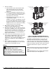
Non-Polarity Sensitive
Line and Neutral
Connections
Ground Tab
Non-Polarity Sensitive
Line and Neutral
Connections
Ground Tab
Non-Polarity Sensitive
Line and Neutral
Connections
Ground Tab
Non-Polarity Sensitive
Line and Neutral
Connections
Ground Tab
Old Style
New Style
Figure 2: G960 Model with Right-Handed Top
Adjustment Regulator with Bottom Pressure Tap
The G960 is supplied with three 1/4 in. (6.35 x 0.8
mm) male tabs, and connections should be made
using 1/4 in. (6.35 x 0.8 mm) female, fully insulated
push-on terminals. The earth ground is clearly labeled.
Route the electrical connection for the valve solenoid
actuators from the burner sequence control to the
valve.
Note: Electrical connections can also be made using
pre-wired electrical plugs (DIN 43650 Form B [ISO
440]).
Note: All wiring must be in accordance with national
and local electrical codes and regulations.