
User Manual

2 H19 Series BASO Automatic Shutoff Pilot Gas Valve Installation Instructions
5. Attach the thermocouple securely to the pilot
burner (H19A_ valves only). Connect the
thermocouple lead nut to the power unit terminal.
Tighten the thermocouple lead nut finge r tight
plus an additional maximum of 1/8 turn. Do not
overtighten.
6. Attach the pilot gas line to the pilot burner fitting
and to the pilot gas outlet of the H19 valve
(H19A_ valves only).
!
WARNING: Risk of Explosion or Fire.
Verify that there are no gas leaks by testing with
appropriate equipment. Never use a match or lighter
to test for the presence of gas. Failure to test
properly can lead to an explosion or fire and may
result in severe personal injury or death.
7. Check for leakage:
a. Shut off the gas at the main manual shutoff
valve and open the pressure co nnection
between the manual shutoff valve and the H19
valve.
b. Connect air tubing with a maximum pressure
of 1-1/2 times the valve’s maximum operating
pressure (as indicated on the valve) to the
opened pressure connection.
c. Paint all valve body connections with a rich
soap and water solution.
If bubbles occur, this is an indication of a leak.
To stop a leak, tighten joints and connections.
Replace the part if the leak cannot be stopped.
If bubbles do not occur, remove the air tubing
and close the pressure connection.
8. Perform the Checkout section before leaving the
installation.
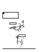
Manual Shutoff
Valve
Reset
Button
3 in. ( 76.2 m m )
Sediment Trap
H19A_ V alve
Thermocouple
Lead
Pilot Burner
Ga s Line
X
X
X
indi cate s possi bl e
loca tions for ot her contro ls.
Figure 1: Typical H19A_ Installation
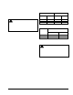
Manual Shutoff
Valve
Reset
Button
H19ME
Gas Valve
Gas Supply
to Burner
Thermocouple
Connection
3 in. ( 76.2 mm)
Sediment Trap
X
indicates possible
location fo r ot her controls.
X
Figure 2: Typical H19ME Installation