
User Manual


H19 Series BASO Automatic Shutoff Pilot Gas Valve Installation Instructions 3
Setup and Adjustments
Checkout
Make sure all components are functioning properly by
performing the following procedure.
Checkout for H19A_ Valv es
!
WARNING: Risk of Explosion or Fire.
Follow this or an equivalent checkout proce dure
after installation. Before leaving the installation,
verify that the gas valve functions properly and that
the system has no g a s leaks. Gas leaks can lead to
an explosion or fire, and may result in severe
personal injury or death.
1. Test all joints and connections for leaks with a
rich soap and water solution. If leaks occur, see
Step 7 in the Installation section.
2. Close the manual shutoff valve and pilot valve
and wait at least 5 minutes for unburned gas to
escape from the appliance, then reopen the
valves.
3. Push the reset button of the BASO® power unit
and light the pilot burner. Continue to h old the
reset button for 30 to 45 seconds or until the pilot
remains burning wh en the reset button is
released.
4. Set the thermostat to the highest setting. The
main burner ignites from the pilot burner.
5. Set the thermostat to the lowest setting. The main
burner extinguishes.
6. Extinguish all flames by closing the manual
shutoff valve. Verify that the main valve drops out
within 90 seconds. Reope n the valve.
7. Relight the pilot burner.
8. Check the millivoltage (mV) output of the
thermocouple and milliampere (mA) dropout
range at the BASO power unit terminal to be sure
that they meet the values in Table 1 and Table 2.
Step-by-step procedures for these checks are
included with the Y99AB-4 BASO Test Kit
Application Note (Part No. 24-8711-838).
9. Observe at least three complete operatin g cycles
to make sure that all components are fu nctioning
correctly.
10. Return the thermostat to a normal temperature
setting before leaving the installation.
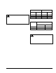
Table 1: Thermocouple Output
Thermocouple mV Range
Lead
Type
Turn
Down
Normal Not Less
Than
K15
4 mV 20-28 15
K16
4 mV 25-35 17
K19
4 mV 25-35 17
Table 2: Dropout Range
mA Range of Power Unit
Assembly
Series
Number
Low High
H19A_
100 300
H19ME
45 165
Checkout for H19ME Valves
(Catalytic Heater Application)
!
WARNING: Risk of Explosion or Fire.
Follow this or an equivalent checkout proce dure
after installation. Before leaving the installation,
verify that the gas valve functions properly and that
the system has no g a s leaks. Gas leaks can lead to
an explosion or fire, and may result in severe
personal injury or death.
1. Turn on the main gas supply to the system.
2. If the heater is equipped with a thermostat, set
the thermostat to the highest setting.
3. Turn on the power to the electrical elements.
4. Wait 15 minutes. Depress the reset button of the
BASO power unit. The button should return to the
original position and internally open the valve
allowing gas to flow to the heater.
Note: If the valve does not stay open when
the reset button is released, it may be necessary
to wait an additional few minutes and then
depress the reset button again.
5. When the catalytic reaction is well e stablished,
turn off the power to the electrical elements.