BatteryMINDer© Model 12248-A-ODY INSTRUCTION MANUAL BatteryMINDer® Model 12248-A-ODY Odyssey-Specific Charger / Maintainer / De-Sulfator with “At-The-Battery” Temperature Sensor 9LL=JQ'#( =J ¸ Charger / Maintainer / Full Time De-Sulfator 12-Volt @ 8 Amp Model 12248-A-ODY ODYSSEY-SPECIFIC 8A For Lead-Acid Batteries ONLY VDC Electronics, Inc. 800-379-5579 (ET) www.batteryminders.
BatteryMINDer© Model 12248-A-ODY TABLE OF CONTENTS Safety Instructions........................................................... 3 - 7 Preparing To Charge...................................................... 5 Charger Location......................................................... 5 DC Connection Precautions............................................. 6 Qualifying Your Battery....................................................... 8 Testing A Sealed, AGM-Odyssey Battery...............................
BatteryMINDer© Model 12248-A-ODY WARNING Underwriters Laboratories (UL) REQUIRED SAFETY INSTRUCTIONS TO REDUCE THE RISK OF FIRE, ELECTRIC SHOCK, OR INJURY TO PERSON, OBSERVE THE FOLLOWING: 1. Do not expose charger to rain or snow. It is designed to operate ONLY INDOORS. 2. USE of any attachment not specifically recommended by the battery charger manufacturer for use with this exact model of charger may result in risk of fire & electric shock or injury to person. 3.
BatteryMINDer© Model 12248-A-ODY To reduce risk of battery explosion, follow these instructions and those published by the battery manufacturer and the manufacturer of any equipment you plan to use in the vicinity of the battery. Review cautionary markings on the products and the engine. 8. PERSONAL PRECAUTIONS when working with or near a lead acid battery: a. Someone should be able to hear your voice or close enough to aid you when working near a lead acid battery. b.
BatteryMINDer© Model 12248-A-ODY NEVER CHARGE A FROZEN BATTERY OR ONE AT A TEMPERATURE ABOVE 123° F. PREPARING TO CHARGE a. If necessary to remove battery from equipment to charge. Always remove ground terminal first. Turn off all accessories in the vehicle, so as not to cause an arc. b. Be sure area around battery is well ventilated while battery is being charged. Force gas vapors away by using a piece of non-metallic material as a fan. c. Clean battery terminals.
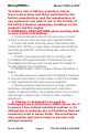
BatteryMINDer© Model 12248-A-ODY DC CONNECTION PRECAUTIONS a. Connect and disconnect DC output clips from battery only after removing charger power cord from outlet. b. Attach clips to battery posts and twist or rock back and forth several times to make good contact. This tends to keep clips from slipping off terminals and reduces risk of sparking. FOLLOW THESE INSTRUCTIONS WHEN BATTERY IS INSTALLED IN EQUIPMENT (VEHICLE, PWC, BOAT, TRACTOR, ETC.) A SPARK NEAR BATTERY MAY CAUSE BATTERY TO EXPLODE.
BatteryMINDer© Model 12248-A-ODY Do not connect clip to carburetor, fuel lines, or sheet metal body parts. Connect to heavy gauge metal part of frame or engine. h. When disconnecting charger, disconnect charger from AC outlet, then remove clips from vehicle chassis, and battery posts. Operating instructions for charge information. FOLLOW THESE STEPS WHEN BATTERY IS OUTSIDE OF VEHICLE OR EQUIPMENT. A SPARK NEAR THE BATTERY MAY CAUSE BATTERY EXPLOSION. TO REDUCE RISK OF A SPARK NEAR BATTERY: a.
BatteryMINDer© Model 12248-A-ODY QUALIFYING YOUR BATTERY: Preliminary Requirements NOTE: The BatteryMINDer has no electrical output unless it is connected to a healthy battery. Testing the BatteryMINDer with a volt or an Amp meter without the unit being connected across a good battery will result in a false reading. If you experience any problems, or are not sure of how to properly use or connect your BatteryMINDer, please e-mail our technical support at: techsupport@vdcelectronics.
BatteryMINDer© Model 12248-A-ODY Failure to test a “rested” (see pg. 9) battery will cause false readings. Be certain to read and understand all safety related instructions (pages 3 to 7) before proceeding further. 2. Measure battery’s voltage, without any load attached. If the voltage is less than 12.4 volts (Typically 50% of charge) the battery may be too heavily sulphated to be fully recoverable. If voltage is 12.
BatteryMINDer© Model 12248-A-ODY Simplified Operating Instructions (Read and understand ALL Safety Instructions on pages (3 -7) and Qualifying Your Battery (pgs. 8 -11) before proceeding) 1. Attach battery connector (either clips or ring terminal assembly) to output cordset of charger. Use either type, but not both at same time. 2. Attach charger output to battery’s terminals. RED sleeve indicator = Positive +, Black = Negative -. If lit RED, reverse charger connectors on battery terminals. Rev.
BatteryMINDer© Model 12248-A-ODY 9LL=JQ'#( =J ¸ Charger / Maintainer / Full Time De-Sulfator 12-Volt @ 8 Amp Model 12248-A-ODY VDC Electronics, Inc. 800-379-5579 (ET) www.batteryminders.
BatteryMINDer© Model 12248-A-ODY LED INDICATOR FUNCTIONS - TABLES 3 (TOP) &4 A&B (BOTTOM) Battery Condition Indication Battery connected before charge:Vb<11V YELLOW Vb<11V GREEN If pressing Reset Button in the charging stage Battery sulphation checked: STOPS CHARGING AND ALLOWS RESET OF ALL SELECTIONS Vb<11V YELLOW Vb<11V GREEN Battery sulphation checked: Vb<12.85V* YELLOW Vb<12.85V* GREEN *12.85-V for AGM-ODYSSEY battery POWER / ERROR LED Status - (Power / Error and Charge LEDs) GREEN A.C.
11 1 7 8 6 5 1) Battery clip cordset w/ qwik connect plug (pgs.13, 16) 2) Ring terminal cordset w/ qwik connect plug (pgs. 13, 16) 3) Mounting tabs 4) Input power cordset (pg. 13, 18) 5) Output cord w/ qwik connect plug (pg. 13, 16) 6) Temperature sensor input connector (pg. 17) 7) Charge rate selection button (pgs. 13, 17, 18) 12 2 10 9 8) Battery type selection button (pgs. 13, 17, 18) 9) Start / reset selection button (pgs.
BatteryMINDer© Model 12248-A-ODY Detailed Operation Instructions Model 12248 After carefully reading and understanding the Safety Instructions contained in this manual (pages 3 to 7) and having evaluated your battery as described in Qualifying Your Battery (pages 8 to 10) you are properly prepared to begin using your charger. 1. Attach output cord of charger to either the Battery Clip(s) Assembly (BCA) (supplied) or the Ring Terminal Assembly (RTA) (supplied) depending on your preference.
BatteryMINDer© Model 12248-A-ODY the mating plug of the RTA. Push firmly and do not leave any space between them. Correct polarity and a good connection will be your reward. Attach the BCA to the proper battery posts, clamps or screw terminals, depending on type of battery. ALWAYS connect the negative (Black) clip to a metal grounding point (Negative ground installations such as most modern cars, trucks, boats, RVs, etc.) as far away from battery as possible for maximum safety.
BatteryMINDer© Model 12248-A-ODY output connections to the battery. 6. The Charge – Float LED Indicator will light GREEN within 15 seconds. The charger will now begin charging by first checking the battery to determine its voltage and ability to accept a charge. Should the battery not have a normal fully discharged voltage (10.5-V minimum) the unit will begin charging in the “Soft-Start” mode to determine if the battery can be safely charged.
BatteryMINDer© Model 12248-A-ODY and conditions, proceed to restart the charger by pressing the Stop / Restart button and allow charger to begin charging battery again. If battery is not defective it should be able to be fully charged after being restarted. After sufficient time has lapsed the GREEN charge LED Indicator will blink confirming when / if battery is now fully charged.
BatteryMINDer© Model 12248-A-ODY potentially hazardous emergency may exist cease using the product immediately and call (800) 379-5579 Ext 201 (ET) Monday – Friday or contact our tech support at ext. 206. Standard operating questions, clearly answered in this manual, will not be answered by phone. Rev.
BatteryMINDer© Model 12248-A-ODY MAINTAINING MULTIPLE BATTERIES BatteryMINDer 12248-A-ODY maintenance charger Desulphators can be used to maintain up to six (6) 12-volt batteries at a time, providing each battery is fully operational (no dead-dying cells), free of sulphate and meeting the minimum full charge “rested” (see pg. 9) voltage of 2.13 volts / cell, after being fully desulphated.
BatteryMINDer© Model 12248-A-ODY connect multiple batteries together for charging purposes using less than #18 Gauge insulated wire. VDC Electronics, Inc. does not make nor can it supply or recommend, any type of wire harness to connect individual batteries for the purpose of charging them in groups, due to the many battery terminal sizes and configurations that exist. See diagram (adjacent) for the various and most common multiple battery configurations.
BatteryMINDer© Model 12248-A-ODY Troubleshooting - Model 12248-A-ODY We use the word “Indicator” to mean the various LEDs (Light Emitting Diodes) showing the various faults, modes, and conditions of the battery and / or charger. The words “unit”, “charger” or “recharger” means your model 12248-A-ODY BatteryMINDer. Problem: Power ON indicator does not light Solution: Check electrical outlet.
BatteryMINDer© Model 12248-A-ODY be so large it may require a second full recharge. Repeat recharge. 3. If recharging multiple batteries, 2 or more complete recharge cycles may be needed. Repeat full recharge. If still RED - blinking, you may need to charge each battery separately.
BatteryMINDer© Model 12248-A-ODY DETAILED SPECIFICATIONS VDC Model No. 12248-A-ODY 8A MCU controlled H.F. Battery Charger Note: This equipment has been tested and found to comply with the limits for a Class B digital device, pursuant to part 15 of the FCC Rules. These limits are designed to provide reasonable protection against harmful interference in a residential installation.
BatteryMINDer© Model 12248-A-ODY DETAILED SPECIFICATIONS VDC Model No. 12248-A-ODY (con’t.) Charging Output Control Characteristics Charging Flow: Battery condition detect>SoftStart Charge>Bulk Charge Absorption Charge>Sulphate Check>Float Charge>Float Pulse Charge SoftStart Charging Activity conditions: 1) Battery Voltage is over 3 Vdc and less than 10.
BatteryMINDer© Model 12248-A-ODY DETAILED SPECIFICATIONS VDC Model No. 12248-A-ODY (con’t.
BatteryMINDer© Model 12248-A-ODY DETAILED SPECIFICATIONS VDC Model No. 12248-A-ODY (con’t.) Battery sulphation check period (After absorption charge is finished): 10 minutes Unloaded output voltage when battery is disconnected: 0.5 Vdc (max.) Output short-circuit current when battery disconnected: 5mA dc (max.) Battery flow back current (to the charger) when connected to 12V battery, AC Power disconnected: 30 (max.
BatteryMINDer© Model 12248-A-ODY DETAILED SPECIFICATIONS VDC Model No. 12248-A-ODY (con’t.) Transformer Transformer Type: Ferrite core transformer Rising Temperature of Transformer: 80º C Max.
Model 12248-A-ODY BatteryMINDer© 14.6-Volt 10.5-Volt 3-Volt start Soft Start (0.5A/1A/2A) (6 Hours timer limited) Full Time Desulphator Bulk Charge (8A 20 Hours timer limited) Odyssey/AGM Mode:14.6-V @ 24ºC (with Temperature compensation) Absorption Charge AGM Type = Odyssey / AGM 20 hours Max (Time-Out) Sulphate Float Charge Check (10 min.) (one hour) Time Full Time Desulphator Float-V = 13.7 Float Pulse Charge (PWM) (1A/2A/4A Max.
BatteryMINDer© Model 12248-A-ODY FOR REPAIR OR REPLACEMENT In the event that you believe your product may be defective, you MUST speak to a VDC Electronics technician at 1-800-379-5579 x206 (ET) before proceeding further. If after speaking with our tech support personnel it is necessary to return the unit, you MUST request an RMA number.
BatteryMINDer© Model 12248-A-ODY NOTES: Rev.
BatteryMINDer© Model 12248-A-ODY Guarantee and Warranty NOTE: ALL returns must be authorized by VDC Electronics after speaking to a VDC Electronics technician at 1-800-379-5579 x206 ET. Please see Page 32 for details. Rev.
BatteryMINDer© Rev.