
Specifications


Dekker Vacuum Technologies, Inc. – DuraVane/12 9
SHUT-DOWN PROCEDURE
To stop the vacuum pump unit, press the STOP button. A built-in anti-suck-back valve will prevent oil
from the oil reservoir being sucked back into the pump cylinder.
SEQUENCE OF OPERATION
The following sequence of operation is a description of how the DuraVane rotary vane vacuum pump
system should operate. The description is general to cover simplex to multiplex (more than one pump)
systems. It is assumed that all start-up procedures have been followed. Ensure that pump reservoirs
are filled with oil (see “Start-up Procedures”, page 8). If unsure about the function of one of the
electrical controls mentioned below, see the “Electrical Controls” section (page 13) for a description of
the component. If any of the below described events do not occur as expected, see the “Trouble-
shooting “ section (page 18).
Once the power connection to the system has been made, the following should occur:
If disconnects or circuit breakers are installed on the control panel, and are turned to the ON
position, the system will be energized. If POWER ON indicating lights are installed on the panel,
the lights will be illuminated.
If any other lights are illuminated, try resetting the ALARM RESET button. If the light does not go
out see the “Trouble-shooting” section (page 18).
If HAND-OFF-AUTO selector switches are installed and are turned to the HAND mode, the
pump(s) will immediately start. If PUMP ON light(s) are installed on the panel, they should light up
to indicate pump operation. We suggest that each pump be tested (“bump started”) in the HAND
mode initially to check rotation of the pump. Rotation is marked by an arrow on the motor or
pump housing. When in HAND mode, the pump(s) will run continuously unless an alarm
condition is triggered. If such a condition occurs, see the “Trouble-shooting “ section (page 18).
When the HAND-OFF-AUTO selector switch is placed in the AUTO mode, the pump(s) will
operate from the vacuum switch(es) (if installed). In multiplex pump systems, each vacuum
switch is set with a differential as well as an offset relative to the next switch. The switches should
not be set identically. For details on setting the vacuum switches, see the “Accessories and
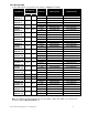
Protective Devices” section (page 13) in this manual. Below is an example for a duplex
system.The differential for each switch is 3”Hg. The offset between the two switches is 1”Hg.
PUMP
PUMP ON
PUMP OFF
Pump 1 (lead pump)
@ 17”Hg
@ 20”Hg
Pump 2(lag pump)
@ 16”Hg
@ 19”Hg
The switches are set in this manner so that if pump 1 (lead pump) cannot satisfy demand and the
vacuum level drops below 16”Hg, the lag pump (2) will start up. It will turn off when the vacuum
level reaches 19” Hg, unless a “10 minute mimum run” timer is installed.
All multiplex systems are supplied with “Automatic alternation” and “Frequent stop/start protection”
unless otherwise specified.
“Automatic alternation” allows the pumps to operate equally (even run time) by alternating each
pump whenever the pump(s) shut down. When alternation occurs, the “lead” pump becomes the
“lag” pump and the “lag” pump becomes the “lead” pump.
“Frequent stop/start protection” is used to allow the pump(s) to operate a minimum amount of
time. The time period is factory-set at 10 minutes. This allows the pump(s) to warm up and
eliminates frequent starting of the pump(s) which can cause premature coupling failure and
breakdown of electrical components. The pump(s) will continue to operate after the vacuum level
has been satisfied. In order to maintain the desired vacuum level, a “vacuum relief valve” can be
supplied with the system. If vacuum level is critical a “vacuum relief valve” is essential. See the
“Accessories and Protective Devices” section (page 13).
If the pump(s) are not alternating and/or are frequent starting, one of the electrical components
may be defective. Contact the factory for more information.