BHG730SS-AUS / BHG750SSAUS / BHG930SS-AUS Gas hobs el 1
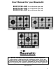
User Manual for your Baumatic BHG730SS-AUS BHG750SS-AUS BHG930SS-AUS 70 cm 5 Burner gas hob 75 cm 5 Burner gas hob 90 cm 5 Burner gas hob NOTE: This User Instruction Manual contains important information, including safety & installation points, which will enable you to get the most out of your appliance. Please keep it in a safe place so that it is easily available for future reference; for you or any person not familiar with the operation of the appliance.
Contents Environmental note 5 Important safety information 6–8 Specifications BHG730SS-AUS BHG750SS-AUS BHG930SS-AUS Electrical details Gas details Gas hob surface layout 9 – 13 9 10 11 12 12 13 Using the gas hob Before first use Switching the hob on Automatic ignition with flame failure device Energy saving tips 13 - 15 13 13 - 14 14 14 - 15 Cleaning Cleaning the hob top After each use Cleaning the hob burners Maintaining the cast iron pan stands 15 - 16 15 16 16 16 Installation Positioning Unpac
Environmental note o The packaging materials that Baumatic uses are environmentally friendly and can be recycled. o Please discard all packaging material with due regard for the environment.
Important safety information Your safety is of the utmost importance to Baumatic. Please make sure that you read this instruction booklet before attempting to install or use the appliance. If you are unsure of any of the information contained in this booklet, please contact the Retailer where you purchased your unit from. General Information o This appliance is designed for domestic household use and for the cooking and frying of domestic foodstuffs.
Child Safety o Baumatic strongly recommend that babies and young children are prevented from being near to the appliance and not allowed to touch the appliance at any time. During and after use, all surfaces will be hot. o If it is necessary for younger family members to be in the kitchen, please ensure that they are kept under close supervision at all times. o Older children should only be allowed to utilise the appliance when supervised.
Cleaning o Cleaning of the hob should be carried out on a regular basis. o IMPORTANT: Before attempting to clean the appliance, it should be disconnected from the mains and cool. o Great care should be taken whilst using this appliance and when following the cleaning procedure. o You should not use a steam jet or any other high pressure cleaning equipment to clean the appliance.
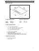
Specifications BHG730SS-AUS Product dimensions: Aperture dimensions: Depth: Width: Height: Depth: Width: 500 mm 685 mm 35 mm 480 mm 560 mm Product specifications: o o o o 1 1 2 1 x x x x 3.00 3.80 1.75 1.
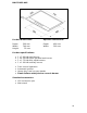
BHG750SS-AUS Product dimensions: Aperture dimensions: Depth: Width: Height: Depth: Width: 500 mm 740 mm 35 mm 480 mm 560 mm Product specifications: o o o o 1 1 2 1 x x x x 3.00 4.20 1.75 1.
BHG930SS-AUS Product dimensions: Aperture dimensions: Depth: Width: Height: Depth: Width: 500 mm 860 mm 35 mm 480 mm 830 mm Product specifications: o o o o 1 1 2 1 x x x x 3.00 4.20 1.75 1.
Electrical details Rated Voltage: Supply Connection: Max Rated Inputs: Mains Supply Lead: 220 - 240 Vac 50 - 60 Hz 3 A (double pole switched fused outlet with 3mm contact gap) 0.006 kW 3 core x 0.75mm² (Type RR-F marked) Gas details Connection: Type: Rp ½ (ISO R7) Natural Gas (20.9 mbar) Alternative LPG G30 (28-30 mbar) For future reference please record the following information which can be found on the rating plate and the date of purchase which can be found on your sales invoice.
Gas hob surface layout BHG730SS-AUS A = 3.80 kW triple crown (wok) burner B = 3.00 kW rapid burner C = 1.75 kW semi-rapid burner D = 1.00 kW auxiliary burner E = Control panel BHG750SS-AUS/BHG930SS-AUS A = 4.20 kW hyper-gas dual (wok) burner B = 3.00 kW rapid burner C = 1.75 kW semi-rapid burner D = 1.00 kW auxiliary burner E = Control panel Using the gas hob Before first use IMPORTANT: You should clean the hob surface (see “Cleaning and maintenance” section).
o The minimum setting is at the end of the anti-clockwise rotation of the control knob. o All operation positions must be selected between the maximum and minimum position. o Never select a knob position between the maximum and off position. o The symbol on the control panel, next to the control knob will indicate which gas burner it operates.
o The diametre of the bottom of the pan should correspond to that of the burner. o The burner flame must never extend beyond the diametre of the pan. o Use flat bottomed pans only o When possible, keep a lid on the pan whilst cooking. o Cook vegetables with as little water as possible, to reduce cooking times. IMPORTANT: Always place pans centrally over the hob burners and position them so that the handles cannot get accidentally caught or knocked off.
After each use o Remove the pan stands and wipe the appliance over with a soft, damp cloth that has been put into warm soapy water. The cloth should be wrung out after being taken out of the soapy water. o Dry the appliance by rubbing the surface with a soft, clean cloth. o We would recommend that an appropriate stainless steel cleaner and polish is regularly used on the stainless steel surfaces of this appliance.
Installation The installation must be carried out by a GASSAFE registered installer, in accordance with the current version of the following. o AS/NZS 3000: 2007 Wiring Regulations o 2010 Electricity Safety Regulations Positioning The adjacent furniture must be able to withstand a minimum temperature rise of 85°C above the ambient temperature of the room it is located in, during periods of use.
o The edges of the hob must be a minimum distance of 55 mm from a side or rear wall. o 700 mm between the highest point of the hob surface (including the burners) and the underside of any horizontal surface directly above it. o 400 mm between the hob surface, providing that the underside of the horizontal surface is in line with the outer edge of the hob. If the underside of the horizontal surface is lower than 400 mm, then it must be at least 50 mm away from the outer edges of the hob.
BHG750SS-AUS BHG930SS-AUS o Cut a hole in the worktop that corresponds with the relevant drawing for your hob on pages 18 - 19. All models o IMPORTANT: You must have a gap of at least 25 mm between the underneath of the appliance and any surface that is below it.
o Carefully turn the hob upside down and place it on a cushioned mat. o Apply the sealing strip (A) provided around the edge of the appliance. o The protective covering must be removed from both sides. o Do not leave a gap in the sealing agent or overlap the thickness. o IMPORTANT: Do not use a silicon sealant to seal the appliance against the aperture. This will make it difficult to remove the hob from the aperture in future if it needs to be serviced.
o On the underneath of the hob, adjust the clamps into a position that is suitable for your worktop. Then fully tighten the screws (C) to secure the hob into position. Gas connection This appliance must be installed by a competent person in accordance with the current versions of the following UK (United Kingdom) or ROI (Republic of Ireland) Regulations and Safety Standards or their European Norm Replacements.
o If it is installed in a room with a volume that exceeds 11m³, then no air vent is required. o If there are any other fuel burning appliances in the same room the current edition of BS 5440: Part 2: should be consulted to determine air vent requirements. o Ensure that the room containing the hob is well ventilated, keep natural ventilation holes or install a mechanical ventilation device (mechanical cooker hood).
o Put the gas seal into the elbow. o Fully tighten the elbow and seal onto the gas rail. o The elbow MUST be pointing in a downwards direction. o Gas pressure may be checked on a semi-rapid hob burner. Remove the appropriate injector and attach a test nipple. Light the other burners and observe that the gas pressure complies with the gas standards in force. o IMPORTANT: On completion carry out a gas soundness test. Gas adjustment (Conversion to LPG) All work must be registered engineer.
o Unscrew the injector (B) and replace it with the stipulated injector for the new gas supply (see table below). GENERAL INJECTORS TABLE Kind of gas Burner Nozzle Ø (mm) Natural gas (Methane) Auxiliary 0.9 Semi-rapid 1.18 Rapid 0.55 Wok 3,3 1.6 Wok 3,8 1.75 Wok 4,2 In 0,70 / Out 1,15 L.P.G. Auxiliary 0.53 (Butane/Propane) Semi-rapid 0.69 Rapid 0.9 Wok 3,3 0.97 Wok 3,8 1.05 Wok 4,2 In 0,45 / Out 0,65 Gas power (Mi/h) 4 7 12 13.2 15.2 16.8 3.7 6.5 11.1 12.2 14 15.
Minimum flow adjustment for hob gas taps. All work must be registered engineer. carried out by a GASSAFE IMPORTANT: Always isolate the hob from the electricity supply before changing the injectors and/or adjusting the minimum flow of the burners. o Switch the burner on and set the knob at the minimum position. o Remove the knob from the tap and place a small bladed screwdriver in the centre of the tap shaft.
Gas tap maintenance These maintenance operations MUST ONLY be carried out by a GASSAFE registered engineer. IMPORTANT: Before carrying out any maintenance operations, disconnect the appliance from the gas and electricity supplies. If a gas tap becomes stiff to operate, then you should proceed as follows: o Remove the control knobs, pan supports, burners, hob fixing screws and clamps. o Remove the hob from the worktop and remove any underside protective covers.
o Reconnect the gas tap, perform a gas soundness test and then reassemble the hob. Electrical connection This appliance must be installed by a qualified person in accordance with the latest edition of the I.E.E. Regulations and in compliance with Baumatic’s instructions. Before connecting the appliance, make sure that the supply voltage marked on the rating plate corresponds with your mains supply voltage. o Cable type: H05 RRF 3 core x 0.75 mm³ (Type RR-F marked).
My appliance isn’t working correctly IMPORTANT: If your appliance appears not to be operating correctly, then you should disconnect it from your mains supply and then contact the Service Department on telephone number 1800 444 357. DO NOT ATTEMPT TO REPAIR THE APPLIANCE YOURSELF. Please note that if an engineer is asked to attend whilst the product is under guarantee and finds that the problem is not the result of an appliance fault, then you may be liable for the cost of the call out charge.
Think Appliances Pty Ltd. 416-424 Barry Rd Coolaroo VIC 3048 Sales Telephone 1300 132 824 Service Telephone 1800 444 357 Website www.thinkappliances.com Applico Ltd. P.O. 92900 Onehunga, Auckland, New Zealand 1061 Website www.applico.nz United Kingdom Baumatic Ltd., Baumatic Buildings, 6 Bennet Road, Reading, Berkshire RG2 0QX United Kingdom Sales Telephone (0118) 933 6900 Website: www.baumatic.co.