Manual Absolute encoder with CANopen® Baumer Electric AG Hummelstrasse 17 CH-8501 Frauenfeld Phone +41 52 728 11 22 Fax +41 52 728 11 44 sales.ch@baumer.com www.baumer.com 08.18 Subject to modification in technic and design.
Contents 1 Version overview ......................................................................................................................................... 4 2 Safety and operating instructions .............................................................................................................. 5 3 3.1 Product Assignment .................................................................................................................................... 6 Absolute encoder .............
9.1 9.2 9.3 9.4 9.5 Non-redundant encoder ............................................................................................................................... 16 Redundant encoder ..................................................................................................................................... 17 Error behavior .............................................................................................................................................. 17 Error Injection ......
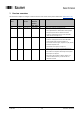
1 Version overview This document is subject to changes. In order to have the most current version please download on www.baumer.com Document index Date Firmware version CANopen Revision Number Obj. 1018 Author Changes 0001 11.07.17 From V01-03 0003.0000h blk Initial version replaces all draft documents 0002 11.9.17 From V01-04 0003.
2 Safety and operating instructions Intended use The encoder is a precision measuring device that is used to record positions and speeds. It provides measuring values as electronic output signals for the subsequently connected device. It must not be used for any other purpose. Unless this product is specially labeled, it may not be used for operation in potentially explosive environments.
3 Product Assignment 3.1 Absolute encoder Product Product-Code Device Name EDS-file Absolute encoder multiturn (single channel and redundant version) 0x0070 EAMxxx MT EAMxxx_0x0070.eds Absolute encoder singleturn 0x0071 EAMxxx ST EAMxxx_0x0071.eds Baumer_EAM580_360_CANopen_MA_EN_Rev0003.0000h_Index0004.docx 06.08.
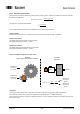
4 System Overview 4.1 General The encoder is a rotary measuring system with a CANopen interface. It supports scaling and presetting. In consideration of “CAN in Automation” (CiA) Profile 406 for Encoders, it’s an Absolute rotary encoder - Class C2. The redundant encoders are galvanically isolated, for non-redundant encoders galvanical isolation on request. 4.2 Supported Profiles Following CANopen profiles are supported: CiA 301 / Version 4.1 (Communication) CiA 305 / Version 1.
4.4.3 Position Range The range of the position is depending on the position step setting (object 6001h-0 and Object 6002h-0). The total range can be read from object 6002h-0. The range is 0…(Value Object 6002h)-1. 4.4.4 Speed range There are two objects, which can be used for the speed information. 0x6030-1 This object provides a 32-Bit Speed information, which has the unit [Steps/sec]. The range for object 6030h-1 Speed encoder A is -8000’0000h…7FFF’FFFFh.
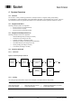
4.4.5 Electronic gear function The electronic gear function divides the position value by the gear factor. Therefore it transforms the position value into the view of the application: 𝑒𝑛𝑐𝑜𝑑𝑒𝑟 𝑝𝑜𝑠𝑖𝑡𝑖𝑜𝑛 𝑎𝑝𝑝𝑙𝑖𝑐𝑎𝑡𝑖𝑜𝑛 𝑝𝑜𝑠𝑖𝑡𝑖𝑜𝑛 = 𝑖 The gear factor (i) is defined as followed: 𝑖= 𝐺𝑒𝑎𝑟𝑉𝑎𝑙𝑢𝑒1 𝐺𝑒𝑎𝑟𝑉𝑎𝑙𝑢𝑒2 There are three objects that should be configured to use the electronic gear function. 0x2001-1 Enable Set this object to the value “2” to enable the electronic gear function, while the value “1” disable it.
4.5 Encoder with redundant design In case of redundant design both encoder channels are connected with the same connector to the network. This means both nodes do acknowledge the message of each other, without being connected to a network. For encoders with redundant design the battery voltage is monitored during power off. Following minimum power off time is required for proper detection: Warning Alarm 4.5.
5 NMT Service 5.1 Supported commands Following NMT commands are supported: NMT Command NMT Start Byte 0 0x01 NMT Preoperational NMT Stop 0x80 0x02 NMT Reset NMT Communication Reset 0x81 0x82 NMT Frame: COB ID node ID 5.1.1 Byte 0 xx NMT Reset This NMT command performs a complete reset of the encoder, which can take up to 170 ms until the new bootupmessage is sent (restarting of the micro controller, be aware that all unsaved configurations will be lost). 5.1.
6 SDO service 6.1 General The device supports 1 SDO server (Expedited read/write, segmented read) 6.2 Save/load parameters The device supports saving parameters to a non-volatile memory. 6.2.1 Save Writing “save” to 1010h-x saves the corresponding objects to the non-volatile memory. After a reset or power-on, the parameters are loaded from the non-volatile memory. The SDO request to 1010h-x is answered after the saving of the parameters is performed. 6.2.
7 PDO Service 7.1 General The device supports TPDO1 and TPDO2. PDOs are only transmitted in NMT operational mode. 7.2 PDO transmission types The following transmission types are supported (object 180xh-2): Synchronous transmission (1-240) Asynchronous transmission (255) Manufacturer transmission (254) RTR-only transmission, event-driven (253) Both PDOs support all transmission types. Transmission type 253: The PDO is only transmitted on request (remote transmission request).
7.4.2 Default mapping of absolute encoder The mappings for both PDOs are the same. The position will be transmitted in byte 0..3. ID DLC Byte 0 Byte 1 Byte 2 Byte 3 181h/281h 4 xx xx xx xx Byte 0...3: Position (Object 6004h) 7.5 Timing The minimal cycle time for TPDOs is 1 ms. 7.
8 Emergency Service 8.1 General If there is an error on the device, the device commits an emergency message and sets the corresponding bits in the error register (Object 1001h). Error codes are accessible by the error field (object 1003h-x). A history of maximal 8 error codes is stored in the error field. 8.2 COB-ID The COB-ID for the emergency message can be modified in object 1014h. Default Value: 80h + node ID Changes will be applied immediately.
9 Alarms, warnings, errors, emergency messages and error behavior Figure 5 and Figure 6 show the surveillance mechanisms. If one of them fails, an alarm or warning will be indicated. The behavior upon an error can be defined and is described in chapter 8.3. 9.
9.
9.4 Error Injection The error injection allows testing a system behavior in case of an encoder malfunction. There are two objects that can be used for test purposes to simulate different encoder behaviors. 0x2116-1 Diagnostic Injection An error injection code, written on this object simulates a diagnostic source according to chapter 9.5.and activates the corresponding signaling. For error injection codes please refer to chapter 9.5.
9.5 Encoder Diagnostic Sources The following tables provide a summary of all diagnostic sources supported by the encoder.
10 Heartbeat Service 10.1 General The device supports a heartbeat producer according CiA 301. 10.2 COB-ID The COB-ID for the heartbeat message is 700h + node ID. 10.3 Timing The minimal cycle time for heartbeat messages is 1 ms, which can be configured with object 1017h-0 Baumer_EAM580_360_CANopen_MA_EN_Rev0003.0000h_Index0004.docx 06.08.
11 LSS slave 11.1 General The baudrate and node ID can be configured by LSS (according to CiA 305). Another possibility to change the baudrate and node ID is to access to the objects 2100h and 2101h (see object directory). The LSS service is only available in NMT Stopped Mode. 11.
12 Object directory The following tables provide a summary of all SDO objects supported by the encoder. Object Object number in Hex Name Object name Format U/I = Unsigned/Integer, No. = no of bits, ARR = Array, REC = Record, STR = String Access ro = read only, wo = write only, rw = read write, m = mappable Default Default value on first init Save X = can be stored in the EEPROM Description Additional information 12.
1800h 00h 01h 02h 05h 1801h 00h 01h 02h 05h 1A00h 00h 01h 1A01h 00h 01h 1F80h Transmit PDO1 parameter Largest Subindex COB ID PDO type Event timer Transmit PDO2 parameter Largest Subindex COB ID PDO type Event timer Transmit PDO1 mapping Largest Subindex 1st mapping parameter Transmit PDO2 mapping Largest Subindex 1st mapping parameter NMTStartup REC U8 U32 U8 U16 REC U8 U32 U8 U16 ARR U8 U32 ARR U8 U32 U32 ro rw rw rw 5h 180h+ID FEh 0 ro rw rw rw 5h 280h+ID 1h 0 rw rw 1 6004’0020h rw rw rw 1 6004
ARR U8 U32 U32 U32 U32 U16 Save 4001h Customer EEPROM Largest Subindex CustomerEEPROM[0] CustomerEEPROM[1] CustomerEEPROM[2] CustomerEEPROM[3] Speed sampling interval in ms Access 00h 01h 02h 03h 04h Format Sub-Index Object 2300h Name Default Description Customer EEPROM to save any data ro rw rw rw rw rw 4 0 0 0 0 50 Baumer_EAM580_360_CANopen_MA_EN_Rev0003.0000h_Index0004.docx 06.08.
12.
13 Applications Changing the node ID and baud rate with LSS The node ID and baud rate can be changed without having to use these to address the encoder. With the LSS service, the sensors are addressed and configured via the product code, revision no., vendor ID and serial number. Changing the node ID (node no.) The node ID can be changed in object 2101h between 1 and 127. A save routine should then be executed using object 1010h. On the next initialization, the encoder logs on with the new node ID.
14 Discrepancies to the CIA specifications Sub-Index Object 0x1029 0x6030 Name 1 Error behavior 3 Error behavior 1 Speed value Discrepancy Default Value is 1 instead of 0 (Do not change NMT-State on Communication-Errors. Default Value is 1 instead of 0 (Do not change NMT-State on Communication-Errors. Datatype is Signed32 instead of Signed16 to provide speed information up to 6000rpm with a 14-Bit ST-Resolution Baumer_EAM580_360_CANopen_MA_EN_Rev0003.0000h_Index0004.docx 06.08.
A. Appendix a. Pin Assignments Assignment cable (connection – L) Cable color grey brown white green yellow pink blue red CANopen Non-redundant CAN_GND +Vs 0V CAN_H CAN_L - signal CANopen redundant CAN_GND +Vs 0V CAN_H CAN_L - CANopen + Inc. Non-redundant A+ +Vs 0V CAN_H CAN_L AB+ B- Pin assignment connector 1 x M12 (connection – N) Cable color 1 2 3 4 5 6 7 8 CANopen Non-redundant CAN_GND +Vs 0V CAN_H CAN_L - signal CANopen redundant CAN_GND +Vs 0V CAN_H CAN_L - CANopen + Inc.