Instruction Manual FADK 14I4470/IO FADK 14I4470/S35A/IO FADK 14I4470/S14/IO FADK 14U4470/IO FADK 14U4470/S35A/IO FADK 14U4470/S14/IO Valid as of version 01-02-11
Instruction Manual for FADK 14 with IO Link Contents 1 1.1 1.2 General Information .................................................................................................................... 3 About this Document .................................................................................................................... 3 General Information ...................................................................................................................... 3 2 2.1 2.2 2.
1 General Information 1.1 About this Document These instructions contain information related to commissioning and communications with the Baumer Series 14 photoelectric distance sensor equipped with the IO Link interface. They supplement the installation instructions, already provided with each sensor. These instructions apply to the following sensor versions (software version 01-02-11): FADK 14I4470/IO FADK 14I4470/S14/IO FADK 14I4470/S35A/IO FADK 14U4470/IO FADK 14U4470/S14/IO FADK 14U4470/S35A/IO 1.
2 IO Link Introduction In order to fully understand the various configuration options, these operating instructions describe the most important aspects of the IO Link interface. More detailed information concerning IO Link, together with all specifications, are available at www.IO-Link.com. IO Link is a standard interface for sensors and actuators. Devices (sensors, actuators) are connected to an IO Link master via point-to-point connections.
2.3 IODD (IO Link Device Description) The IODD describes the IO Link device, and can be downloaded at www.baumer.com. It comprises a set of XML and PNG files. An engineering or diagnostic tool reads a sensor’s IODD in order to determine the following: - Identification (manufacturer, designation, part number, etc.); - Communication characteristics (communication speed, frame type, etc.); - Parameters and commands; - Process data; - Diagnostic data (events).
4.1.1.2 Significance of the Status Information Bit 0: Alarm The alarm bit indicates whether an object lies within the measurement value range. Bit0 = 0 → An object lies within the specified measuring range. Bit0 = 1 → There is no object within the specified measuring range. Bit 1: Switch bit In the IO Link communication mode, the switch bit performs the function of a switching output. Bit1 = 0 → There is no object within the the switching range. Bit1 = 1 → An object lies within the switching range.
5 Explanation of the Sensor Configuration Parameters and commands can be used to configure the sensor functionalities. The following sections provide a detailed description of the various configuration options. 5.1 Teaching a User-Specific Measuring Range 5.1.1 Parameter Measuring range work: This parameter covers the currently used beginning and end values for the measuring range.
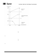
Figure 2: Possible characteristic measuring value curves 5.1.3.1 Example of Numerical Teaching: 1) The measuring range is to be set between 150mm (A) and 300mm (B) (characteristic curve 2). Point A, absolute value in 0.1 mm: Point B, absolute value in 0.
5.1.3.2 Example of Teaching an Object The measuring range is to be taught for an object (characteristic curve 2). Figure 3: Teaching characteristic measuring value curves For an inverted characteristic curve (characteristic curve 3), the distance between the sensor and Measuring range limit A must exceed that to Measuring range limit B. 5.1.
5.2 Teaching a User-Specific Switching Window 5.2.1 Parameter Switching points work: This parameter comprises the currently employed beginning and end points of the switching window. The beginning and end point of the desired switching window can either be directly defined in the parameter (numerical teaching), or it can be automatically set via the interim register when an object is being taught. The parameter comprises two 16 bit components: Switching point A and Switching point B. - Unit: 0.
Figure 4: Possible characteristic switching curves 5.2.3.1 Example of Numerical Teaching: 1) A switching window is to be set between 150mm (A) and 300mm (B) (characteristic curve 2). Point A, absolute value in 0.1 mm: Point B, absolute value in 0.
5.2.3.2 Example of Teaching an Object The switching window is to be taught for an object (characteristic curve 2). Figure 5: Teaching a switching window For an inverted switching window (characteristic curve 3), the distance between the sensor and Switching point A must exceed that to Switching point B. 5.2.4 Hysteresis In the approach direction to the switching window, the sensor switches at the precisely the learned switching points.
5.2.5 Error Handling The learned switching points lie closer together than permitted in the minimum teachable switching window (10mm): • Error message: Interfering parameter (refer to: Table Fehler! Verweisquelle konnte nicht gefunden werden., Fault codes); • Interim register is set to FFFF FFFF hex; • The most recent valid values remain active.
5.4 Average Value Formation 5.4.1 Parameter Average: Number of measurements for which an average is formed. Value range: 0, 2, 4, 8, 16 Factory setting: 0 (no average value formation) 5.4.2 Description Forming an average of an adjustable number of measuring values helps to reduce measurement noise, and thus increase the sensor’s reproducibility and resolution. This reduces the response speed, but the measuring speed remains unaltered.
Overview of SPDUs 6.
Comments CMD Value SPDU Index Table of System Commands mand Name of Com- 6.3 Restore factory setting 0X02 0X82 Restores all original factory settings of the sensor Teach-in 0X02 0XA0 Teach-in of switching point A. The measured distance is written into the interim switching 0X02 0XA1 Teach-in of switching point B. The measured distance is written into the interim switching switching point A Teach-in points register. switching point B Transfer points register.
Application Specific Name 0X18 empty Switching points work 0X40 Switching point A: 50mm Measuring range work 0X42 Measuring range limit A: 50mm Average 0X50 0 (no average value formation) Output function switching output 0X62 0 (Alarm) Nominal value 0X65 7 SPDU name Default value Table of Factory Settings SPDU index 6.5 Switching point B: 400mm Measuring range limit B: 400mm quality parameter BA_FADK14IO-Link_V01-02-11_EN.doc 04.12.
Baumer worldwide Brazil Baumer do Brasil Ltda BR-04726-001 São Paulo-Capital Phone +55 11 56410204 Canada Baumer Inc. CA-Burlington, ON L7M 4B9 Phone +1 (1)905 335-8444 China Baumer (China) Co., Ltd. CN-201612 Shanghai Phone +86 (0)21 6768 7095 Denmark Baumer A/S DK-8210 Aarhus V Phone +45 (0)8931 7611 France Baumer SAS FR-74250 Fillinges Phone +33 (0)450 392 466 Germany / Austria Baumer GmbH DE-61169 Friedberg Phone +49 (0)6031 60 070 India Baumer India Private Ltd.