Manual Absolute encoder with EtherCAT, Power over EtherCAT (PoE) (with bus cover) Firmware version 5.00 and up www.baumer.com 09.14 · 174.02.064/3 Subject to technical and design modifications. Errors and omissions excepted.
Content Page 1. Introduction 4 1.1 1.2 4 4 2. 3. 4. 5. Scope of delivery Product classification Safety and operating instructions Bus cover – functional principle Encoder operating parameters Encoder data 5.1 5.2 5.3 5.4 5.5 5.5.1 5.6 5 6 7 8 PDO (Process Data Object) SDO (Service Data Objects) Parameterization Free Run Mode (default) Distributed Clocks Mode Activation Distributed Clocks under TwinCAT Network management 8 9 17 18 19 19 21 6. Terminal assignment and commissioning 23 6.1 6.2 6.
Disclaimer of liability The present manual was compiled with utmost care, errors and omissions reserved. For this reason Baumer rejects any liability for the information compiled in the present manual. Baumer nor the author will accept any liability for direct or indirect damages resulting from the use of the present information. At any time we should be pleased receiving your comments and proposals for further improvement of the present document. Created by: Baumer IVO GmbH & Co.
1. Introduction 1.1 Scope of delivery Please check the delivery upon completeness prior to commissioning. Depending on encoder configuration and part number delivery is including: Basic encoder, bus cover and CD with describing file and manual (also available as download) 1.
2. Safety and operating instructions Supplementary information This manual is intended as supplement to already existing documentation (e.g. catalogues, data sheet and mounting instructions). The manual must be read carefully prior to initial commissioning of the equipment. Intended purpose of the equipment The encoder is a precision measurement device.
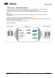
3. Bus cover – functional principle The product family architecture is modular. Depending on what is required from the encoder, the basic encoder and bus covers can be combined at will with the selected bus system. The basic encoders differ in terms of accuracy, ambient conditions and the utilized sensing principle. Bus cover The bus cover accommodates the entire electronics for measured value processing and for Ethernet communication. The bus covers differ by the respectively integrated bus interface.
4.
5. Encoder data 5.1 PDO (Process Data Object) Depending on the configuration, the encoder will provide the following process data (input data): XML file BAUMER Group absolute EtherCAT encoders.xml PDO Mapping 10Byte PDO: (default) 4 Byte Position value 2 Byte Warnings 4 Byte System Time/Speed value Product code 20 Applied in version V5.
5.2 SDO (Service Data Objects) SDOs access is in the TwinCAT System under tab CoE - Online (CANopen over EtherCAT). Since there is a large variety of CANopen device and application profiles they may be applied in EtherCAT slaves. EtherCAT encoders provide partial implementation of the CANopen DS406 encoder device profile. Please consider that every CoE access (mailbox communication) will shortly interrupt generation of encoder input data for the time of mailbox communication.
Object list Detailed explanations on the most important SDO objects Object 0x1000 Device Type SubIndex Data type Access Default EEPROM Significance Values 0 Unsigned 32 ReadOnly Multiturn: 0x00020196 Singleturn: 0x00010196h No Information on device profile and device type Object 0x1008 Device Name SubIndex Data type Access Default EEPROM Significance Values 0 VISIBLE_STRING ReadOnly According to connected basic encoder "GXMMW_H","GXAMW_H","GCMMW_H ","GCAMW_H ", “GBMMW_H ","GBAMW_H " No Device name in A
Object 0x1011 RESTORE Application Parameter Object 0x1011 restores ROM default in device-specific objects (0x6000..0x6FFF) both in RAM and EEPROM. To prevent any inadvertent restore, the signature „load“ must be written in object 0x1011 Subindex 0.
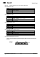
Object 0x1A00 TxPDO1 Mapping SubIndex Data type Access Default EEPROM Significance Values 0 Unsigned 8 ReadOnly SubIndex Data type Access Default EEPROM Significance Values 1 Unsigned 32 ReadOnly SubIndex Data type Access Default EEPROM Significance Values 2 Unsigned 16 ReadOnly SubIndex Data type Access Default EEPROM Significance Values 3 Unsigned 32 ReadOnly 0x2000 System time Yes System time, Speed value 0x2000 = System time, 0x6030 = Speed value No Maximum supported subindex 3 No Position valu
Device-specific objects Object Data in this area are hold volatile in RAM after any change. To save in non-volatile EEprom use object SAVE Application Parameter 0x1010. Object 0x6000 Operating parameters SubIndex Data Type Access Default EEPROM Significance Values 0 Unsigned 16 ReadWrite 0, scaling OFF, CW, Speed Value readout in steps /s Yes Operating parameters Bit 0: Direction of rotation 0 CW 1 CCW Any parameter other than default will only become effective with enabled scaling function (0x6000).
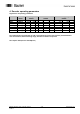
Object 0x6002 Total measuring range SubIndex Data type Access Default EEPROM Significance 0 Unsigned 32 ReadWrite 0x20000000 = 536870912 = 29bit GXMMW_H 0x2000 = 8192 = 13bit GXAMW_H 0x10000000 = 268435456= 28bit GCMMW_H 0x1000 = 4096 = 12bit GCAMW_H 0x80000000 = 2147483648 = 31bit ² GBMMW_H 0x40000 = 262144 = 18bit GBAMW_H Yes Total measuring range in steps optionally programmable.
Object 0x6003 Preset value SubIndex Data type Access Default EEPROM Significance Values 0 Unsigned 32 ReadWrite 0 Yes Optionally programmable position value. In this operation an offset value is calculated and saved in object 0x6509. 0..actual total measuring range (0x6002) -1 Entries ≠ default values are only effective with enabled scaling function (0x6000).
Object 0x6501 Max. measuring units per revolution (max.
5.
5.4 Free Run Mode (default) In "Free Run" mode, a local timer interrupt of the application controller will trip the local cycle which in Free Run is independent of communication cycle and/or master cycle. The encoder will generate the process data in asynchronous cyclic manner. Fig.: Wireshark Network session, encoder input data Baumer_EtherCAT_PoE_5-00_MA_EN.docx 30.09.14 18/30 www.baumer.
5.5 Distributed Clocks Mode Distributed clocks mode enables exactly the same time with all bus users. The encoder can be utilized and configurated as reference clock for synchronisation purposes of both other users and master. Thus a high-precision time base is available throughout the network. The encoder generates process data synchronously to a Sync Signal. The local cycle will be tripped once SYNC0/SYNC1 Event has been received.
Fig.: Local cycle synchronized with SYNC0/SYNC1 Sync 0 Event Sync 0 Event 1C33:3 Shift time time Sync 1 Event Sync 1 Event 1C33:6 Calc and copy time 1C33:5 Minimum Cycle time 1C33:2 Cycle time SSI CLK SPI SS Input Latch Cycle times corresponding to configuration, see chapter Cycle times Baumer_EtherCAT_PoE_5-00_MA_EN.docx 30.09.14 20/30 www.baumer.
5.6 Network management The encoder’s State Machine can be switched in the TwinCAT System Manager under tab Online. EtherCAT State Machine The EtherCAT State Machine (ESM) will control the state of the EtherCAT slave with state-related access and execution of several functionalities. Specific commands by the EtherCAT master are required in each state during slave bootup.
Init Initial state of EtherCAT slave after switch on. There is neither mailbox nor process data communication. The SyncManager channels 0 and 1 for mailbox communication are being initialized by the EtherCAT master. Pre-Operational (Pre-Op) The EtherCAT slave will verify proper mailbox initialising when changing from Init to Pre-Op. Pre-Op enables mailbox communication but not process data communication.
6. Terminal assignment and commissioning 6.1 Mechanical mounting Shaft encoders Mount encoder housing by help of the mounting holes and three screws (square flange: 4 screws) provided at flange. Observe thread diameter and depth. There is an alternative mounting option in any angular position by eccentric fixings, see under accessories. Connect drive shaft and encoder shaft by using an appropriate coupling. The shaft ends must not touch each other.
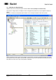
6.2.1 Initialising under TwinCAT system manager The included XML file must be copied into the respective directory: ..\TwinCAT\Io\EtherCAT Start TwinCAT system manager Then proceed as described below. 3 1 2 4 5 6 7 EtherCAT devices should appear like in screen below Baumer_EtherCAT_PoE_5-00_MA_EN.docx 30.09.14 24/30 www.baumer.
6.2.2 Terminal assignment Bus cover shaft / blind hollow shaft - EtherCAT 60 L/A Link/Activity Anzeige/display LED IN OUT 63 Status-Anzeige Status display DUO-LED OUT IN 1 x M12 connector (male), a-coded Pin 1 2 3 4 2 x M12 connector (female), D-coded Assignment UB (10...30 VDC) N.C. GND N.C.
6.3 Display elements 6.3.1 State indicator The bus cover provides a DUO LED (green/red) operating in line with EtherCAT Indicator Specification V0.91.
6.4 Bus cover Power over EtherCAT (PoE) Based on the IEEE-standard 802.3af, the Baumer EtherCAT encoder with PoE bus cover is interacting as PD (Powered Device) with a corresponding PSE (Power Sourcing Equipment) module. Signal and power transmission is by 4-wire standard EtherCAT/Ethernet cable (for example CAT-5). The PSE will identify the encoder as PD after power on by the procedure specified in IEEE standard 802.3af.
6.
6.6 Configuration 10 Byte PDO / 4 Byte PDO / 2 Byte PDO by TwinCAT Default encoder configuration is 10 Byte PDO. As an option, the encoder configuration may be changed to 4 Byte PDO or 2 Byte PDO to enable shorter cycle times where appropriate (see chapter cycle times).
6.7 Speed Value as an alternative to System Time The only configuration to enable the speed value (speed transmission) is 10 Byte PDO. To do so, enter value 0x60300020 in TxPDO Mapping object 0x1A00:3. Enter the desired unit for speed value readout in object 0x6000 bit 12 and the integration time in object 0x6031. Object SAVE Application Parameter (0x1010) will save the parameters in the non-volatile memory.