Manual Absolute Encoder with DeviceNet Firmaware version from 1.02 Baumer IVO GmbH & Co. KG Dauchinger Strasse 58-62 DE-78056 Villingen-Schwenningen Phone +49 (0)7720 942-0 Fax +49 (0)7720 942-900 info.de@baumerivo.com www.baumer.com 05.11 · 174.02.041/3 Subject to technical and design modifications. Errors and omissions excepted.
Contents Page 1. Introduction 3 1.1. 1.2. 3 3 Scope of delivery Product assignment 2. Safety precautions and operating information 4 3. Encoder operating modes 5 3.1. 3.2. 3.3. 5 5 5 Poll Mode Change of status Mode (COS) Cyclic Mode 4. Encoder operating parameters 5 5. Object model 6 6. E/A Entities/Assembly 7 7. Encoder configuration 8 8. Encoder Position-Object 9 9. Terminal assignment and commissioning 12 9.1. 9.2. 9.2.1. 9.2.2. 9.2.3. 9.3.
Disclaimer of liability The present manual was compiled with utmost care, errors and omissions reserved. For this reason Baumer IVO GmbH & Co. KG rejects any liability for the information compiled in the present manual. Baumer IVO nor the author will accept any liability for direct or indirect damages resulting from the use of the present information. At any time we should be pleased receiving your comments and proposals for further improvement of the present document. 1. Introduction 1.1.
2. Safety precautions and operating information Additional information • The manual is a supplement to the documentation which already exists (catalogues, product information and installation manuals). • It is imperative that the manual is read prior to commissioning. Proper use • The encoder is a precision measuring device. It is used exclusively for the detection of angle positions and rotations, and the processing and provision of the measured values as electrical output signals for the next device.
3. Encoder operating modes 3.1. Poll Mode In Poll Mode the encoder will transmit upon request of another user. The data transferred may optionally comprise position data or an additional warnflag and alarmflag. 3.2. Change of status Mode (COS) The encoder will transmit position data without being requested by another user if the actual process value has changed by a certain value (adjustable COS-Delta). 3.3.
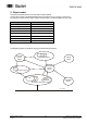
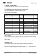
5. Object model The object model describes the encoder object classes applied. The encoder provides a Predefined Master-Slave-Connection-Set. It is a group 2 only Server. The following chart shows the object classes and the number of entities available in each class.
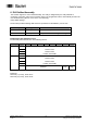
6. E/A Entities/Assembly The encoder supports 2 E/A Entities/Assembly. The entity is designated by the entity attribute 14 (produced_connection_path) of the connection object. The programmed value is automatically stored in the non-volatile memory (service “save” here is not necessary). Entity default setting: 1. The encoder provides following data which are input data from the Master’s point of view.
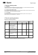
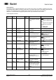
7. Encoder configuration The encoder-specific parameters can be programmed by the parameter object 0Fh. Each object entity refers to a certain attribute of the encoder-position-objects. Amended parameters are not stored in the non-volatile memory until the service „save“ is carried out. Parameter object entities The following chart shows the parameter object 0Fh entities supported by the encoder. Entity No. name Reference to attribute no.
8. Encoder Position-Object The Encoder Position Object is a manufacturer-specific object with class code 2Fh. Entity attributes Due to their different functionality, entity attributes are broken down into two groups. The first group, attribute 1 to 12 comprises the parameters for position calculating. The second group, attribute 90 to 95 comprises the diagnostic functions. Altered parameters are not stored in the non-volatile memory until by service “save”.
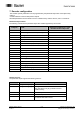
Preset function The preset function supports adjustment of the encoder zero point to the system’s mechanical zero point. The actual encoder position is set to the preset value. The internal offset value is calculated and stored in the encoder. For storage into the non-volatile memory first the service “save” has to be carried out. Attention: It is recommended to apply the preset function only in idle status of the encoder.
Parameter Significance Alarm signals Attribute 83 provides the alarm signals. An alarm is set as soon as the encoder is recognizing a status that may lead to a wrong encoder position. Upon recognising the alarm status, the relevant bit is set to logically high. The alarm is automatically reset after 2.5 s. The alarm flagbit (attribute 85) is also set with every alarm. Warning signals The encoder will transmit warning signals upon the internal encoder parameters being beyond the tolerances.
9. Terminal assignment and commissioning 9.1. Mechanical mounting • Mount the encoder housing using the fastening holes on the flange side with three screws (square flange with 4 screws), paying attention to the thread diameter and thread depth. • Alternatively, the encoder can be mounted in any angular position by using three eccentric fastenings – see accessories. • Connect the drive shaft and encoder shaft using a suitable coupling. The ends of the shafts must not be touching.
9.2.3. Terminal significance Pin 1 2 3 4 5 Terminal DRAIN UB GND B CAN_H CAN_L Micro Connector Pinout Male (Pin) Significance Shield connection Power supply 10...30 VDC Ground connection UB CAN Bus Signal (dominant High) CAN Bus Signal (dominant Low) 9.3. Display elements (status display) A DUO LED (green/red) working in the ‘Combined Module/Network Status’ in line with the DeviceNet specification is providing information on the status of the device respectively of the network.