
Instruction Manual


Manual_GXP8W_EN.doc 13/13 Baumer IVO GmbH & Co. KG
04.05.11 Villingen-Schwenningen, Germany
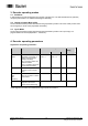
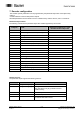
9.2.3. Terminal significance
Pin
Terminal Significance
1
DRAIN Shield connection
2
UB Power supply 10...30 VDC
3
GND B Ground connection UB
4
CAN_H CAN Bus Signal (dominant High)
5
CAN_L CAN Bus Signal (dominant Low)
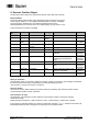
Micro Connector
Pinout
Male (Pin)
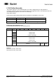
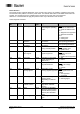
9.3. Display elements (status display)
A DUO LED (green/red) working in the ‘Combined Module/Network Status’ in line with the DeviceNet
specification is providing information on the status of the device respectively of the network.
LED-Colour Status Significance
off not connected
No power supply
- Dupl. MAC-ID check not terminated.
- No power supply
Green flashing Device is active and online
No connections established
The device is operating under normal conditions and
is online, no connection established.
- Encoder not yet configurated by Master
- configuration incomplete or faulty
Green continous Device is active and online
Connections are established
The device is operating under normal conditions and
is online, connection status “established”
Red continous Critical device error or
Critical communication error
The device is in fatal non-corrective error status
- no network communication possible
- double assignment of user address (MAC-ID)
Red flashing Corrective error I/O connections in Time-Out status