Sensor Solutions Motion Control Vision Technologies Process Instrumentation Betriebsanleitung Betriebsstundenzähler ISI34, ISI35 Operating instructions Hour counter ISI34, ISI35 Instructions d’utilisation Compteurs horaires à affichage ISI34, ISI35 Baumer IVO GmbH & Co. KG Dauchinger Strasse 58 – 62 · DE-78056 Villingen-Schwenningen Phone +49 (0)7720 942-0 · Fax +49 (0)7720 942-900 info.de@baumerivo.com · www.baumer.com 04/10 · 171.55.
ISI34, ISI35 Betriebsanleitung 1.5 Montageanleitung LCD-Betriebsstundenzähler isiLine 34/35 Beschreibung Die batteriebetriebenen LCD-Betriebsstundenzähler isiLine 34/35 lassen sich in unterschiedlichste Applikationen einsetzen. Typische Anwendungen sind z.B.: Betriebszeit- und Lebensdauererfassung, Durchlaufzeitmessung, Zeitüberwachung usw. Die Ansteuerung erfolgt über potentialfreie Kontakte oder Spannungsimpulse. 1.
ISI34, ISI35 1.
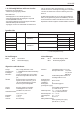
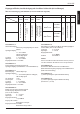
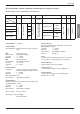
ISI34, ISI35 Eingangsspezifikationen, Anschlussbelegung und einstellbare Zeitbereiche (DC-Ausführung) Bezeichnung Nr. 1 Nr. 3 Nr. 2 INP A Reset INP B Nr. 4 Nr. 5 Reset Enable Nr. 6 Zeitbereich (Mode) GND Nr. 7 Nr. 8 BL – BL + Hintergrundbeleuchtung (+) Schraubklemme Hintergrundbeleuchtung (–) Über einen Steuereingang (Schraubklemme 5) wird der Zeitbereich eingestellt). ISI34.010AX01 NPN PNP Verriegelungseingang für Rücksetztaste NPN. Beschaltet nach GND, Taste freigeschaltet.
ISI34, ISI35 Eingangsspezifikation, Anschlussbelegung und einstellbare Zeitbereiche (AC-Ausführungen) Nr. 1 INP A AC/DC Nr. 2 Common AC/DC Nr. 3 INP B AC/DC Nr. 5 Nr. 4 Reset Enable Nr. 6 Zeitbereich (Mode) GND Nr. 7 Nr. 8 BL – BL + Hintergrundbeleuchtung (+) Bezeichnung Hintergrundbeleuchtung (–) Schraubklemme deutsch Über einen Steuereingang (Schraubklemme 5) wird der Zeitbereich eingestellt).
ISI34, ISI35 Lieferumfang: Digitalanzeige Spannbügel Frontrahmen für Schraubbefestigung, Einbauquerschnitt 50 x 25 mm Frontrahmen für Spannbügelbefestigung, Einbauquerschnitt 50 x 25 mm Dichtung Bedienungsanleitung Hinweis: Dieses Produkt enthält eine Lithium-Batterie. Nicht gewaltsam öffnen, nicht ins Feuer werfen. Temperaturen unter –20 °C und über 70 °C vermeiden! Dieses Gerät enthält eine Lithium-Batterie.
ISI34, ISI35 – Slide the fixing clip from the rear onto the housing, until the spring clamps are under tension and the upper and lower latching lugs have snapped into place. Operating instructions LCD Hour meter isiLine 34/35 1.6 Electrical installation The isiLine 34/35 are battery-powered LCD hour meters. They can be used for various applications. Typical uses are for example: operating time and lifetime measurement, passage time measurement, time monitoring, etc.
ISI34, ISI35 1.10 Failure possibilities and causes Impossible to use the keys: - Key lock input activated If, despite all, your device still does not operate, contact your local representative or call us directly for technical support.
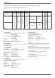
ISI34, ISI35 Input specifications, terminal assignment and adjustable time ranges (DC versions) The time range is set via a control input (screw terminal 5). No. 2 INP A No. 3 INP B Reset No. 4 No. 5 Reset Enable No. 6 Time range (Mode) No. 7 No. 8 GND BL – BL + backlight (+) No. 1 backlight (–) Designation GND = 0 V DC Screw terminal ISI35.
ISI34, ISI35 Input specification, terminal assignment and adjustable time ranges (AC versions) The time range is set via a control input (screw terminal 5). INP A AC/DC No. 2 Common AC/DC No. 3 No. 4 INP B AC/DC No. 5 No. 6 Time range (Mode) Reset Enable No. 7 No. 8 GND BL – BL + Backlighting (+) No. 1 Backlighting (–) designation GND = 0 V DC Screw terminal NPN reset key locking input, Contact with GND. key free. not active reset input AC/DC Timer Enable Input AC/DC ISI35.
ISI34, ISI35 Note: This product includes a lithium battery. Do not open it by force, do not throw it in the fire. Avoid temperatures below –20 °C and above 70 °C!. This device contains a lithium battery. In compliance with the battery directive, we inform you that: Batteries must not be discarded in the household waste, but the law obliges you to bring them to the collection point specifically provided for that purpose. You can send us back the complete devices after use.
ISI34, ISI35 Instructions d’utilisation 1.5 Instructions de montage Compteurs horaires à affichage LCD isiLine 34/35 Description Les compteurs horaires à affichage LCD isiLine 34/35 sont alimentés par batterie. Ils trouvent leur place dans les applications les plus variées, par exemple: mesure du temps de fonctionnement et de la durée de vie, mesure du temps de passage, surveillance du temps, etc. Ils sont commandés par des contacts secs ou des impulsions de tension. 1.
ISI34, ISI35 - Polarité (NPN/PNP) inversée - Pas de raccordement à la masse entre le générateur d’impulsions et le compteur - Dépassement de la fréquence de comptage maximale - Les niveaux des signaux n’atteignent pas le seuil de commutation du compteur Exécutions AC : Utiliser des fils blindés pour les entrées de comptage et de commande afin d’obtenir la résistance CEM maximale. 1.9 Mise en route – L’appareil est-il bien réglé et programmé (fonction ; fréquence de comptage max.
ISI34, ISI35 Caractéristiques des entrées, affectation des bornes et plages de temps réglables (exécution CC) Désignation N° 1 N° 2 INP A N° 3 INP B N° 4 Reset N° 5 Reset Enable N° 6 Plage de temps (Mode) GND N° 7 N° 8 BL – BL + Rétroéclairage (+) Borne à vis Rétroéclairage (–) La plage de temps se règle par l’intermédiaire d’une entrée de commande (borne à vis 5). ISI35.
ISI34, ISI35 Caractéristiques des entrées, affectation des bornes et plages de temps réglables (exécution CA) La plage de temps se règle par l’intermédiaire d’une entrée de commande (borne à vis 5). INP A CA/CC N° 2 Common CA/CC N° 3 INP B CA/CC N° 4 N° 6 N° 5 Plage de temps (Mode) Reset Enable N° 7 N°.
ISI34, ISI35 Etendue de la livraison : Compteur Etrier de montage Cadre avant pour fixation par vis, Découpe d’encastrement 50 x 25 mm Cadre avant pour fixation par étrier, Découpe d’encastrement 50 x 25 mm Joint Instructions d’utilisation Nota : Ce produit comporte une batterie au lithium. Ne pas l’ouvrir de force, ne pas le jeter au feu. Eviter des températures inférieures à –20 °C et supérieures à 70 °C ! Cet appareil contient une pile au lithium.
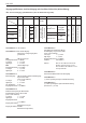
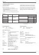
ISI34, ISI35 Anschlussbilder/Connections/Schémas de branchement: DC-Typ: ISI34.010AX01 ISI35.010AX01 DC-Typ: ISI34.011AX01 ISI35.011AX01 max. 30 V DC n.c. INP B Reset max. 30 V DC max. 5 V DC 1 n.c. 2 INP B 3 Reset 1 2 3 Reset 4 Enable Mode 5 Reset 4 Enable Mode 5 GND 6 GND 7 (-) BL (-) BL (+) BL 24 V DC ±20 %, 50 mA 8 (+) BL max.
ISI34, ISI35 Abmessungen/Dimensions/Dimensions: Schalttafelausschnitt/Panel cut-out/Découpe d’encastrement : Abmessungen Einbaurahmen/Frame dimensions/Dimensions du cadre: Schalttafelausschnitt/Panel cut-out/Découpe d’encastrement : Schalttafelausschnitt/Panel cut-out/Découpe d’encastrement : 1 18 Senkung Af3, DIN 74/Countersinking Af3, DIN 74/Fraisure Af3, DIN 74 www.baumer.
Baumer IVO GmbH & Co. KG Dauchinger Strasse 58 – 62 DE-78056 Villingen-Schwenningen Phone +49 (0)7720 942-0 Fax +49 (0)7720 942-900 info.de@baumerivo.com www.baumer.com Irrtum sowie Änderungen in Technik und Design vorbehalten. Subject to modification in technic & design. Sous réserve modifications et d‘erreur dans la technique et le design. R.60340.