Original Operating Instructions BAUMCUT 26.
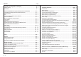
Index page Control Panel / Operating Elements ............................................................... E - 4 Explanation of Pictographs on the Display ...................................................... E - 5 Chapter Survey ............................................................................................... E - 6 Introduction .....................................................................................................
Index Select Language/Measuring Unit ............................................................... K5B - 3 Knife Compensation ................................................................................. K5B - 4 Resting Time for Knife at BDC ................................................................... K5B - 5 Maintenance Cut Counter .......................................................................... K5B - 6 Preset Functions ................................................................
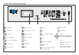
Control Panel / Operating Elements D 7 8 9 i 4 5 6 1 2 3 x C 0 PROGRAMMABLE 1 Automatic ON Automatic OFF Program Data 2 3 Machine Parameter Subtraction Clear input field Auxiliary Program Functions Enter Decimal point Additional Functions Insert; subsequent insertion of Cursor (4 keys: right, left, up, down; Center key: Additional cursor motion; cursor in basic position data Program Information Function Survey (Main Menu) Numerical keyboard Delete Division Correction (of stored
Explanation of Pictographs on the Display Pre clamping time Hand wheel/electr.
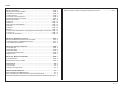
Chapter Survey Chapter Survey Page 1.0 Technical Data/Machine Layout/Transport and Installation of Machine/ Safety Relevant Machine Elements ................................................................................ K1 - 1 2.0 Safety.............................................................................................................................. K2 - 1 3.0 Start Up ...........................................................................................................................
Introduction BAUM cutting machines form a part of the wide range of products manufactured by the BAUM company. Decades of experience in constructing high speed cutting machines and peripheral equipment, together with state-of-the-art engineering and manufacturing procedures, careful testing and highest quality standards ensure the reliability and performance of your BAUM machine.
E-8
1.
1.
1.
1.0 Technical Data/Machine Layout/Transport and Installation of the Machine/Safety Relevant Machine Elements Transport and Installation of the Machine After Unloading • • • Remove all packing and wrapping material Check machine and accessories for damages Check for missing parts Have the machine installed by BAUM service personnel, exclusively! In Case of Complaints The installation of the machine requires special skills which can be guaranteed only by especially trained experts of BAUM agencies.
1.
1.0 Technical Data/Machine Layout/Transport and Installation of the Machine/Safety Relevant Machine Elements Type Plates Type plate Type plate The machine designation including • manufacturer‘s address • model • machine number • date of fabrication • electric. equipment Adolf Mohr Maschinenfabrik 65719 Hofheim/Ts Germany Model is indicated on the machine type plate. K1 - 6 Serial No. /PE AC mfd.
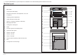
1.0 Technical Data/Machine Layout/Transport and Installation of Machine/Safety Relevant Machine Elements Safety Relevant Machine Elements Front side (operating side) 1 Main switch 2 Light barrier (20 - channel) Capacity to recognize object: 25 mm Min.
1.0 Technical Data/Machine Layout/Transport and Installation of the Machine/Safety Relevant Machine Elements Safety Relevant Machine Elements Accident prevention warning labels at BAUM cutters. Placement of the warning labels Placement of the warning label Label 1 (1x): Label 2 (1x): Label 3 (2x): Warning labels are of little value if the foreseeable user cannot see them at the appropriate time, i.e., before he or she encounters the hazard.
Safety Signs Safety Signs / Warning Signs In order to ensure maximum safety the machine / system is provided with safety signs. Safety signs are either standardized safety signs warning of risks or danger, or warning signs alerting the operating or service staff of - any forbidden actions at the machine / system, and/or - informing about any load limits, such as the max. carrying capacity of the machine and/or its load carrying unit.
1.0 Technical Data/Machine Layout/Transport and Installation of Machine/Safety Relevant Machine Elements Technical Data Permissible Environmental and Operating Conditions • Observe the procedures described in case of malfunctions and the mainte nance intervals indicated. Operate the machine in closed areas, exclusively! Air humidity: Ambient air temperature: 35% - 95% (non condensing) +5°C - +40°C Hydraulic Data Hydraulic pressure, max.
1.0 Technical Data/Machine Layout/Transport and Installation of the Machine/Safety Relevant Machine Elements Technical Data Cutting width 67 cm / 26,38" Clamp opening 8 cm / 3,15" Feed depth 67 cm / 26,38" Voltage supply (3 phase) 200 - 240, 50/60Hz Fusing 3 x 25A Voltage supply (3 phase) 360 - 420V, 50/60Hz Power requirement (main motor): Single phase A C 3 phase 2,2 kW / 3,1 H.P. 2,4 kW / 3,4 H.P.
K1 - 12
2.0 Safety Any person on the user´s premises concerned with the operation, maintenance and repair of the machine, resp.
Foreword to the operating instructions Fundamental safety instructions These operating instructions are designed to familiarize the user with the machine/plant and its designated use. Warning and symbols The instruction manual contains inportant information on how to operate the machine/plant safely, properly and most efficiently. Observing these instructions helps to avoid danger, to reduce repair costs and downtimes and to increase the reliability and life of the machine/plant.
Observe all safety instructions and warnings attached to the machine/plant. See to it that safety instructions and warnings attached to the machine are always complete and perfectly legible. In the event of safety-relevant modifications or changes in the behaviour of the machine/plant during operation, stop the machine/plant immediately and report the malfunction to the competent authority/person.
Warning of special dangers Any procedure impairing the safety at the machine must be refrained from. In particular do not - reach into the range of knife and clamp, use auxiliary tools (e. g. material gauge) - reach into the range between clamp and cutting material gauge (backgauge with rake) on the machine rear table - with Autotrim function: entering the opened table crack to remove residual cuttings. Only do that with the machine switched off.
3.0 Start Up Attention! Prior to any commissioning and any change of shifts the operating staff has to check if the safety-related machine elements are in proper service condition and complete.
3.0 Start Up Switching Machine ON Attention! Prior to any commissioning and any change of shifts the operating staff has to check if the safety related machine elements are in proper service condition and complete. D 7 i 4 1 8 9 5 6 2 3 x C 0 PROGRAMMABLE 1. Turn main switch (2) from "0" to "I" < Control voltage is switched on. After several seconds display shows Program data display > Turning Machine OFF 1. Wait until automatic operations have ended. 2.
3.0 Start Up Measurement Display and Measurement System After switching on, the "Program Data Display"* appears on the screen. Program Data Display It shows among other things... A on the upper screen (A): ACTUAL POSITION on the lower screen (Nominal position input field, B): NOMINAL POSITION INPUT The actual position (A) shows the real backgauge position in mm, cm, inches or sun = 1/10 shaku (Japan).
K3 - 4
4.
4.0 Manual Operation Setting of Measurements (Backgauge Movement) by Hand 1. Press electronical hand wheel and hold it in this position; turn hand wheel to the left or to the right D 7 8 i 4 5 6 1 2 3 = forward movement of the backgauge = reverse movement of the backgauge 9 x C 0 PROGRAMMABLE The backgauge speed gets faster by turning the electronical hand wheel to the left/right .
4.0 Manual Operation Clamping and Cutting Starting the cut: D 7 i 4 1 8 9 5 6 2 3 x C 0 PROGRAMMABLE Push both cut buttons (4) simultaneously. (Hold buttons until knife is on upstroke)! Interrupting the cut: Release one or both cut buttons (clamp and knife stop immediately and move back to initial position). Continuing the cut: 4 Release and simultaneously push both cut buttons.
4.0 Manual Operation Light Barrier The lightbarrier (17) forms a curtain of invisible beams in front of the knife. Any obstacle in the beams will stop clamping and cutting. In that case the clamp can still be lowered with the pedal (indication of cutting line).
4.0 Manual Operation Continuation: Light Barrier Meaning of LEDs in display unit Display unit in the left-hand part of the light barrier (receiver side): D1 D2 D3 D4 D5 D6 Meaning _________________________________________________________________ on on on on off off Protect. area „unobstructed“, light reception excellent off on on on off off Protect. area „unobstructed“, light reception good off off on on off off Protect.
4.0 Manual Operation Clamping with False Clamp Plate The clamp plate avoids clamping marks on sensitive stock. Attaching false clamp plate: Push plate against clamp from underneath until you hear guide pins (6.1)snap. 6.2 Removing of false clamp plate: 1. Lower clamp with pedal approx. 2" above table and fix it in this position. 2. Press two screw drivers simultaneously into the drillings (6.2) in the clamp. False clamp plate is dropped! K4 - 6 6.
5.
Introduction Functions of the menu keys* A position (cut size) entered via numerical keyboard can be stored permanently. Any number of cut sizes necessary for the processing of a pile of material can be input and stored. All the data (cut sizes, information, additional functions) concerning one particular order can be stored under one program number. Cut sizes can also be stored automatically when a cut is triggered.
5.0 Automatic Operation Basic Displays 1. Program Data: key 3. Main Menu (Function Survey): key 2. Program Information: key 4.
5.0 Automatic Operation Contin.: Basic Display: Program Data Conc. 1 Program Head shows: Conc. 5 P: Program number of indicated program with memory segment e.g. 1A = program 1, memory segment A and program protection (asterisk) S: Quantity of step numbers assigned by the program Display of Additional functions Display of the pictograph/s representing the Additional function/s Conc. 6 Status display "Actual machine function" Display of the pictograph representing the actual machine function Conc.
5.0 Automatic Operation Basic Display: Program Information Press key Program Information display: The Program Information display shows information about the currently selected program. These pieces of information can be complemented by entering an order number or order name in clear text. The alpha input is performed via a keybord displayed on the screen. Input capacity: max. 16 characters! For the storing of information - refer to page K5A - 20.
5.0 Automatic Operation Basic Display: Program Directory Basic display "Program Directory" Press key The program-survey shows all stored programs of the selected memory with the following data: (screen top): e.g.: - A - = memory "A" e.g.: 1/ = program number e.g.: 1/1575 = order number/order name PROGRAM NUMBER 5_VAC. = display of number of the next free program of the actual memory section Note: One "page" of the display can show a maximum of 4 programs.
5.0 Automatic Operation Basic Display: Main Menu (Function Survey) Press menu key Basic display "Main Menu" (Function Survey): Menu "Language/Select measuring unit" The Main Menu (Function Survey) contains a selection menu of various machine functions. It provides the user with the possibility to select functions which „accompany“ the sequence of operation, i.e. such functions are either set at the start of the operation or in case of need.
5.0 Automatic Operation Cursor Movement in Basic Display Cursor = indicator Cursor keys The basic displays contain two kinds of cursor : A. Cursor "step" ( in program data section) B.
5.0 Automatic Operation Automatic Backgauge Adjustment through Numerical Keyboard Program data display: Conditions: Automatic OFF A Measurement input with metric system (cm) Example: Size Key input 1. 30,735 2. Positioning, press 2 x shortly ________________________________________________________________ B Measurement input in inches Same way of input as for metric system however value in inches entered as a fraction: Example: Size Key input 1. 12 1/2" 2.
5.0 Automatic Operation Deletion of a Wrong Input Press < input section is deleted > Moving Backgauge to a Nominal Position (Positioning) 1. Enter nominal position 2. Press twice shortly < backgauge moves to nom. pos. forward or backward > Deletion of a wrong input Press Input Error: Value of Nom.
5.0 Automatic Operation Selection of a Free Program / Display of the Next Free Program Display (example): Possible in all 4 basic monitor displays! 1. Press key "Program Selection" < Selection menu appears; Assignment display in the right-hand section of the image: display of free programs of selected memory segment A in % > Make selection "Program Number": 2. Press key 3. Enter desired program number 4. Press key < Program Data display of the program appears > or 5.
5.0 Automatic Operation Selecting a Program Possible in all 4 basic monitor displays! Example: Two calling modes: A. According to program number B. According to order number/order name A. According to Program number: 1. Press key 2. Select "program number" with key 3. Enter desired program number 4. Press key "Program selection" < menu appears > < program data display of selected program appears > B.
5.0 Automatic Operation Continuing: Selecting a Program Select a character using the cursor keys (with the equal key you can jump over five characters in a line), then press cursor key "Home" * 4. Press key 5. Press key Numerical keyboard < character is inserted into input section > (multiply) D i 7 8 9 4 5 6 x 1 2 3 < the desired program (order) appears in the data section, the resp. order number/order name is faded in.
5.0 Automatic Operation Storage of Measurements Only in Program data display! 1. Select free program 2. Enter desired size with numerical keyboard (e.g. size 23,5 cm) 3. Press key "Enter" < beep sounds; nominal position is on step 1 in program data section >: Note: Display can show up to 3 steps (lines). When entering step 4 former step 1 will disappear into screen memory.
5.0 Automatic Operation Setting Up a Cutting Program, Example 1 Two side trim on size DIN A3 untrimmed size 31 x 43 cm Cut sizes to be stored on program no. 2A 1. 2. Cut size: Cut size: 30,5 cm 42,5 cm Key input: 1. Call program 2A 2. 2. 42,5 cm (Enter) 1. 30,5 cm 3.
5.0 Automatic Operation Setting Up a Cutting Program, Example 2 Four edge trim with following cuts; starting size DIN A3 untrimmed 31 x 43 cm; finish size DIN A4 (21 x 29,7 cm) 1. 30,5 cm 4. 42,0 cm Cut sizes: 1. 2. 3. 4. 5. 30,5 cm 42,5 cm 29,7 cm 42.0 cm 21,0 cm 5. 21,0 cm Cut sizes to be stored in program 5A Key input: 1. 2. 42,5 cm Call program 5A 2. 3. 29,7 cm (Enter) 3. 4. 5. 6.
5.0 Automatic Operation Correction of an Input Error A. Correcting before storing (prior to pressing of key "Enter" ; nom.pos. is shown in input section 1. Press key < nom. pos. in input section disappears > 2. Enter correct size/comment 3. Press key B. Correcting after storing "Enter" (Nom. pos. is shown in program-data section) 1. Select step number (cursor) 2. Press key 3. Enter right size 4. Press key Example: "Correction" "Enter" size 23.
5.
5.0 Automatic Operation Running a Cutting Program Example: Setting a cutting program, example 1 1. Call program 2A < display shows program data of program 2A > 2. Switch on Automat forward: press key Operation mode: AUTOMATIC 3. Press key 4. Align stock 5. Make cut 2 x shortly < backgauge moves to 1. cut size > After cut: - backgauge advances approx. 5 cm / 2" (ejector) - then reverse to 42.500 (with air table) 6. Turn stock by 90° and line up 7.
5.0 Automatic Operation Storing of Program Informations Press key "Program Information" The Program Information display shows information about the currently selected program. These pieces of information can be complemented by entering an order number or order name in clear text. The alpha input is performed via a keybord displayed on the screen. Input capacity: max. 16 characters! Storing "Order" 1. Press key 2.
5.0 Automatic Operation Deletion of a Step Number 1. Select program 2. Select step (with cursor) 3. Press key "Delete" 4. Press key "Enter" < program data display appears > < size (step) is deleted.
5.0 Automatic Operation Deletion of One/Several Program(s) Possible variations: 1. 2. 1. Deleting in Program Data Display and Program Information Display Deleting in Program Directory Display Deleting in Program Data Display and Program Information Display Attention! In the Program Directory display only the current shown program can be deleted. 1. Press key program selection 2. Select "Delete program/s" with key < menu appears > < program data display appears > 3.
5.0 Automatic Operation Deletion of Complete Memory 1. Select Program Directory: press key 2. Press key "Program Selection" 3. Press key "Delete program(s)" 4. Press keys < menu appears > < menu appears > D 7 8 9 i 4 5 6 1 2 3 x C 0 5.
5.0 Automatic Operation Inserting of Measurements into a Program 1. Select program < program data display appears > 2. Select step that will receive new measurement (cursor) 3. Press key 4. Enter measurement (e.g. 30.500) 5. Press key "Insert" < step is left open for entry > "Enter" Storing of Measurements According to Printed Image 1. Select free program 2. Press key "Actual - Nominal Position" < actual size appears in input section > 3. Align stock at backgauge 4.
5.0 Automatic Operation Calculator Functions Conditions: Automatic OFF The digital and calculator keys enable 4 basic arithmetic operations. They can be used to calculate cut sizes. The calculation and the solution are always displayed in the input section. Note: Pressing of keys "+", "-", "x" and ":" will always result in the display of the last digital input of the previous calculation. This will be deleted during the new input.
5.
5.0 Automatic Operation Machine Functions and Additional Functions (Menu Keys) Operating panel with menu keys: Machine Functions Machine functions are basic functions of the machine. They can be changed for the program sequence.
5.
5.0 Automatic Operation Select Language / Measuring Unit Select "Main Menu" (Funtion survey) Press key < menu appears > Select function (LANGUAGE or MEASURING UNIT): 1. Key input: (language) or (measuring unit) 2. Select language or measuring unit: Enter number Service After selection display of machine identification (electronical type plate) appears. Possible inputs: • Machine equipment • BAUM safety check • Name of inspector You can jump to the next input line by pressing key .
5.0 Automatic Operation Knife Compensation Calibration to compensate for knifes of different thickness Select menu "Knife" with key Select function: Select "Knife compensation": Enter correction with keys or ; store with Knife change - see chapter "6.
5.0 Automatic Operation Resting Time for Knife at BDC Adjustment of the time knife remains in its bottom dead center (BDC). Adjust time: 1. Select menu "Knife" with key 2. Select "Resting time for knife at BDC" with key 3.
5.0 Automatic Operation Maintenance Cut Counter Operation: Shows maintenance intervals. Has been set to 100.000 cuts by manufacturer. Counter starts at "0" or other preset amount and counts upward. After reaching 100.000, at every start-up, the operation display will read OBSERVE MAINTENANCE SCHEDULE Select maintenance cut counter Set counter: 1. Enter number of cuts via keyboard 2.
5.0 Automatic Operation Preset Functions Selection of "Main Menu": Correction of Current Position Basic measurement = distance between backgauge rake and knife This menu allows the inspection and correction of the basic position (actual position) of the machine. If the basic measurement indicated corresponds to the actual backgauge position: Select "Current Position OK“ . If the basic measurement indicated does not correspond to the actual backgauge position: Select "Correct. current pos.
5.0 Automatic Operation Continuing: Preset Functions Select function "Preset functions": Scan Reference Positionj In the case of a machine malfunction the reference point can be newly scanned with this function. Procedure: 1. Select "Scan reference position" < display change > 2. Confirm "Clear table surface" < display change > 3.
5.0 Automatic Operation Adjustment of Display Contrast In this menu image the display contrast can be adjusted in four steps. Procedure: Enter step number of desired contrast (1-4) via keyboard.
5.0 Automatic Operation Block Programming Selection of Block Programming with key Block Programming = automatic programming Blcok Programming is fitted with graphic operator prompting for the automatic generation of a cutting program for printed and unprinted sheets. The required cutting sizes and remarks are automatically stored in a free program. There are 3 variations of Block Programming with up to 8 available block programming modes. The selection of a variation is done by cursor keys.
5.0 Automatic Operation Block Programming Setting up a Block Programming Example: Variation 1, selection: 1 Angular cut 1. Select cutting mode 2. Menu: "Angular cut" 1 Orig. sheet size 2 Sheet size tables 3 Lay guide lft / ri With this menu it is able to enter the original sheet size manually or to select a sheet size from a sheet size table. Angular cut 3. Selection: Enter orig. sheet size 4. Enter "Original sheet size X", confirm with key 5.
5.0 Automatic Operation Block Programming Confirm the sheet orientation or turn sheet orientation (observe paper grain) Menu: 8. 1 Sheet orient. OK 2 Turn sheet e.g.: "Sheet orient. OK" Enter Edge trim 9. Enter "Edge trim width X", confirm with key 10. Enter "Edge trim width Y", confirm with key 11.
5.0 Automatic Operation Block Programming Example: Variation 1, selection: Four trim cut "Four trim cut" 1. Select 2. Menu: 3. e.g.: Enter Orig. sheet size 4. Enter Original sheet size X, confirm with key 5. Enter Original sheet size Y, confirm with key 6. or e.g.: Sheet size tables 7. Select left-hand lay side (=default) or right-hand lay side: 1 Orig.
5.0 Automatic Operation Block Programming Example: Variation 3, selection : 3 Four trim cut with labels 1. Select "Four trim cut with labels" 2. Menu: 1 Orig. sheet size 2 Sheet size tables 3 Lay guide lft / ri With this menu it is able to enter the original sheet size manually or to select a sheet size from a sheet size table. 3. e.g.: Enter Orig. sheet size 4. Enter Original sheet size X, confirm with key 5. Enter Original sheet size Y, confirm with key or 6. e.g.: Sheet size tables 7.
5.0 Automatic Operation Block Programming Enter Edge trim 10. Enter "Edge trim width X", confirm with key 11. Enter "Edge trim width Y", confirm with key 12. Menu 1 Final size entry 2 Sheet size tables 13. e.g.: "Enter final size" 14. Enter "Final size X", confirm with key 15. Enter "Final size Y", confirm with key or 16. e.g.: "Sheet size tables" 17. Select desired sheet size by means of the cursor keys and confirm with key Menu 1 Label orient. OK 2 Turn material 18.
5.0 Automatic Operation Block Programming Example: Concerning variant 3, selection: 1. Select 2. Selection menu: 2 four-side trim with labels and trim cuts "four-side trim with labels and trim cuts" 1 initial sheet size 2 Table of sizes 3 Lay guide lft / ri In this menu, a selection can be made between: - the manual input of the initial sheet size and label size - the selection of an initial sheet size and label size from a table of sizes with trimouts upon label cutting. 3.
5.0 Automatic Operation Block Programming Enter outside trim 9. Enter outside trim "X" confirm with button 10. Enter outside trim "Y" confirm with button 11. Selection menu: 12. Example: "Input of final size": 13. Enter final sheet size "X" confirm with button 14. Enter final sheet size "Y" confirm with button 1 Input of final size 2 Format tables or 15. Example: "Table of sizes": 16.
5.0 Automatic Operation Block Programming 20. Enter label sequence "X" confirm with button 21. Enter label sequence "Y" confirm with button Explanation: X: 1 / 1 = 1 Label + 1 trimout in X-direction Y: 2 / 1 = 2 Labels + 1 trimout in Y-direction 22. Selection menu: 1 Finish input 2 Select cutting sequence 23. Example: "Sel (ect) cutting sequence": 24. Select desired cutting sequence, such as e. g. "cutting sequence crosswise: 25.
5.0 Automatic Operation Menu Key: Additional Functions Key "Additional Functions" Jogging mark Key "Additional Functions" includes the following operations*: Jogging mark Ejector OFF Help The running of cutting programs can be further automated by using Additional Functions. The Additional Function can be selected on the operating panel under menu key "Additional Functions" It is possible to store several Additional Functions into one step number.
5.0 Automatic Operation Storage of Additional Functions with Cut Size 1. Enter cut size 2. Press key 3. Enter number of desired Additional Function 4. Press key < additional function menu is opened > < for identifying the stored Additional Function the symbol is displayed behind the step number > Subsequent Storing of Additional Functions 1. Select program < program data display appears > 2. Select step number 3. Press key "Correction" 4. Press key < add.
5.0 Automatic Operation List of Additional Functions Additional function: Jogging mark Ejector OFF Operation: Knife block: A stored jogging mark for exact line up against backgauge and side guides will block the cut at this position.
K5C - 4
5.
5.0 Automatic Operation Cut and Record 1. Select free program 2. Press key 3. Select "Cut and record" 4. Make cut < actual size is stored upon every cut > "Auxiliary Functions" After program generation: Switch function off by selecting it again (when program is changed or "Automatic On" is activated function is switched off automatically!) Sheet Size Tables List of DIN sizes A0 - A9. The corresponding sizes (lengths or widths) can be selected by cursor and transferred to the input section.
5.0 Automatic Operation Subtraction Repetition Unit Fast and easy programming of a sequence of equal cut sizes. Procedure: 1. Move backgauge to desired initial position 2. Select "Auxiliary Functions" with key 3. Select 4. Enter label size (e.g.: 2 cm) 5. Make cut "Subtraction Repetition Unit" activated function After each cut backgauge moves forward 2cm until backgauge reaches the front limit position. Note: The label size can be changed during this process.
K5D - 4
5.
5.0 Automatic Operation Prepressure Time With spongy or soft stock it is recommended to increase the clamping time before the actual cut. The adjusted pre-pressing time is the period between start of clamping and initiation of cut. For this purpose, 9 pre-clamping grades are available.
6.
6.0 Knife Change Knife change The knife change should only be carried out by specially trained personnel Tools required: 1 Knife wrench 1 Knife guard 2 Knife holders D 7 i 4 1 8 9 5 6 2 3 x C 0 PROGRAMMABLE Removing the knife 1. Select display "Main menu" (Function survey) with key . i Make selection "3 Knife". Select "2 Knife change" 2. Bring turning knob (i), located beneath the front table, to position "Knife change" 3.
6.0 Knife Change Knife Change Mounting the knife 1. Replace cutting stick or turn same over (see page K6 - 5) 2. Turn adjusting cam (e) to the "0 - position" by means of the knife wrench 3. Screw knife handles (c1) into the black bordered bolt holes (f) of the new knife g 4. Take knife out of the knife box b 5. Remove knife handles (c1) and mount knife guard (c) 6.
6.0 Knife Change Knife Change Knife adjustment D 7 i 4 1 8 9 5 6 2 3 x C 0 PROGRAMMABLE 1. Bring turning knob (i), located beneath the front table, to position "Knife change". 2. Press both cut buttons and keep them pressed until knife bar stops automatically at the lower position. 3. Loosen center knife bolt (knife should now drop down to the cutting stick. If necessary use the knife wrench to push down the knife against the cutting stick).
6.0 Knife Change Changing of cutting stick The BAUM sinus cutting stick is made of high resistance plastic material. Due to the unusual wavy design a tight fitting in the table grove is assured without the need for glue or screw. Each cutting stick is useable 4 times as they are turned around. Removing of cutting stick Tool needed: normal screw driver 1. Lift cutting stick slightly on the left side cutting stick stop 2. Prey out cutting stick carefully from left toward the right.
K6 - 6
7.
7.0 Malfunctions/Breakdowns Electrical Malfunctions/Breakdowns Electrical malfunctions of the machine will appear in the status display in plain text and with an error number. The operator is warned by a beep sound. In that case, the operator has to decide whether it is an • • • operation error, programming error, malfunction of the machine. Remedy for operating error (programming error): • • check program data or input, resp.
7.0 Malfunctions/Breakdowns Start - Up Breakdown: Scan Reference Point/Auxiliary Mode Malfunction: After machine has been started, display shows after turning off the machine: "SCAN REFERENCE POINT" Cause: Machine was shut off during backgauge movement Remedy: Scan reference point 1. Select "(1) Reference position scan" < prompt appears: clear the table > 2. Select "(1) Confirm when table empty" < prompt appears: go to reference position > 3.
7.
8.0 Maintenance Prior to any maintenance work, cut off machine and disconnect power supply. Caution! All the cables marked with the symbol are still alive (mains voltage) even if the main switch is shut off.
Basic information about servicing and maintenance work • Always turn off the machine and disconnect the power supply before undertaking any maintenance work. • In the event of defective safety equipment, e.g. safety light barriers, protective covers, etc., the machine/system must be taken out of operation and repaired immediately. • All safety signs on the machine/system must be in impeccable and easily identifiable condition. Replace safety signs if this is not the case.
HYDRAULIC We recommend to have oil changed and unit checked by BAUM and/or authorized personnel. Attention when bleeding hot oil - danger of burning! Oil change: approx. every 6000 hrs. Fill in oil up to middle of oil level indicator! Quantity (liters): 22,5 BACKGAUGE DRIVE (grease lubrication) Lubrication by grease gun! 1. 2. 3. Move backgauge to position 42 cm (16,5 inches)! Remove lid (C) at backgauge drive guard Grease spindle via lubricating nipple 2 - 3 strokes with the grease gun are sufficient.
BATTERIES FOR DATA STORAGE To be replaced only by BAUM service or agencies. Batteries inside machine are used for data storage. Replacing after approx. 5 years CLEANING OF DISPLAY 1. 2. Turn off machine Use glass cleaner and soft lint-free rag. MAINTENANCE INTERVALS Maintenance should only be carried out by BAUM Service exclusively! 5 hrs. per day equal: Please call for maintenance or service ahead of due date! The address of the representation can be read from the plate on the machine. 6.
For these documents we reserve all legal rights. They are not to be copied or made known to others, without express agreement, regardless of what form they might take. Violations will entail liability for damages.
Service:______________________________________________ _____________________________________________________ Mr./Mrs.: _____________________________________________ BAUM USA 1660 Campbell Road • Sidney, Ohio 45365 Phone 937/492-128 or 800/543-6107 Fax 937/492-7280 © 1999 BAUM USA Printed in USA Technical alterations reserved 11/76/PD/76D1133 (V1.2.