
bavarianDEMON AXON Manual V1.5


QUICK INTRODUCTION
MOUNTING POSITION
Important is an orientation exactly aligned with the level of the main rotor or rotor shaft in all 3 axes, i.e. the assembly surface must
be orthogonal (90°) or parallel to these. Contrary to normal tail gyros, this is particularly important to ensure that the head stabilization
maintains constant attitude, even during pirouettes. All four main orientation directions are possible (see software), plus mounting it
inverted or even vertical. So alltogether, 24 options for the installation orientation are possible.
AVOIDING VIBRATIONS
The mounting surface must be sturdy and vibrate as little as possible. The closer the unit is tted to the rotor shaft, the less vibrations
is usually present.
In the case of internal combustion engines, it is particularly important to take care with this issue to reduce invisible vibrations. If the
housing should noticeably vibrate extremely while the engine is running, we recommend choosing a different installation position that
is protected better against vibrations.
AVOID CLOSE PROXIMITY TO HEAT SOURCE
Keep a distance from the exhaust tube, ESC and motor. Using the system inside a fuselage, make sure to supply plenty of fresh air.
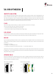
USE THE SUPPLIED MOUNTING TAPE
Clean the mounting surface properly. Use the thicker and softer tape for internal combustion engines only, and the thin tape for all
other models.
Do not additionally lash the housing as this will restrict the damping effect of the foam tape. For the same reason, do not tightly lash the
connecting cables (servos and receiver) and do not lay them under tension in a straight line, but in a gentle bend leading to the system.
Switch off ALL mixers in the transmitter. The swash type / mixer is set only in the system and in accordance with the linkage type. In
the transmitter, select an unmixed standard program (CCPM/H1), and disable the collective-to-tail mix.
All functions like gyro menu, AVCS menu and pitch-throttle curve remain in the transmitter. Moreover, Expo and Dual Rate settings are
allowed to be used in the transmitter, but only after the initial setup has been completed.
SERVO ENUMERATION
The following diagrams show the enumeration of the servos, and thus the correlation in connecting them to the AXON, dependent on
the swash type. Note: 3-servo swash types may have the center servo linkage located either to the front or rear of the main shaft. The
servo enumeration remains the same: #1 is left, #2 is right, and #3 is center.
H3-120° H3-140° H3/H4-90° H4-90°+45°
4
PREPARING THE REMOTE CONTROL
INSTALLATION