IP Series Codec Installation Instructions Please read this manual before installing your equipment
IP Series Codec Installation and Operating Instructions IMPORTANT The first few pages of these instructions contain important information on safety and product conformity. Please read, and ensure that you understand this information before continuing.
Installation and Operating Instructions IP Series Codec CONTENTS Product Safety ............................................................................................................................................................................................ 4 Electromagnetic Compatibility (EMC) ...................................................................................................................................................... 4 EU Conformance Statement .........................
IP Series Codec Installation and Operating Instructions PRODUCT SAFETY Please follow these instructions as you install your IP Series Codec and retain them for its lifetime. If you encounter any problems contact your agent. Installation is only to be carried out by competent, qualified and experienced personnel. Wire in accordance with the National Wiring regulations applicable to the country of installation. Failure to do so can result in death or injury by electric shock.
Installation and Operating Instructions IP Series Codec OVERVIEW Baxall Destiny IP Series Codecs comprise a single hardware unit that may be configured to function as an encoder or as a decoder. Codecs are available in 1, 2 or 4-way units housed within a single 19 rack-mounted enclosure.
IP Series Codec Installation and Operating Instructions IP-CODEC GENERAL LAYOUT Single-way IP CODEC Front and Rear Panels (IP-ENC1-R and IP-DEC1-R) Two-way IP CODEC Front and Rear Panels (IP-ENC2-R, IP-DEC2-R and IP-ENC1DEC1-R) Four-way IP CODEC Front and Rear Panels (IP-ENC4-R, IP-DEC4-R and IP-ENC2DEC2-R) Note: On combined Encoder/Decoder units, the decoder modules are always on the right hand side of the unit when viewed from the front.
Installation and Operating Instructions IP Series Codec CONNECTORS OVERVIEW Each channel of the IP-Codec has a common set of input and output connectors whose function is described below. Note that certain connectors are used differently depending on whether the unit is functioning as an Encoder or a Decoder. Encoder Connectors Decoder Connectors POWER CONNECTIONS The encoder is powered from an AC supply of 120-240VAC at 50-60Hz via the supplied IEC connector.
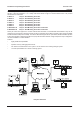
IP Series Codec Installation and Operating Instructions CAMERA CONNECTIONS (ENCODER ONLY) Analogue Camera Connection Analogue cameras are connected to an IP Codec that is configured to function as an Encoder. Up to four analogue cameras can be connected to each channel of an IP Codec as shown below. Note that only one camera can be viewed at any one time i.e. the unit does not provide multiplexing functionality.
Installation and Operating Instructions IP Series Codec VIDEO OUTPUT CONNECTIONS (DECODER ONLY) A system monitor is connected to the VID I/O BNC connecter of an IP Codec that is configured to function as a Decoder as shown below. AUDIO CONNECTIONS (ENCODER AND DECODER) Audio Line in and Line out signals are available on each channel of an IP Codec via a stereo 3.5mm jack socket. SETTING THE IP ADDRESS The user may configure the IP address, sub-net mask and default gateway.
IP Series Codec Installation and Operating Instructions SERIAL PORT CONNECTIONS Destiny IP Codec units can be connected via an RS232, RS422 or RS485 network. The illustrations below show the different connection details for each of these protocols. The DIP switches shown set the biasing/termination for each type of network.
Installation and Operating Instructions IP Series Codec SERIAL PORT CONNECTIONS RS422 (4-wire) Network Connection and Biasing/Termination Details Note that the switch settings for all END units are the same, and for all MID units. CONFIGURATION SWITCHES Each channel of the IP Codec contains two rows of eight DIP switches. The basic function of the dip switches is described below.
IP Series Codec Installation and Operating Instructions CONFIGURATION SWITCHES Video Termination Switches These switches allow you to individually select whether each video source is terminated or not. The termination impedance is 75W. The default setting for a device configured as an Encoder is for each video source to be terminated. Note, where the Codec is configured as a Decoder, these switches should always be set to OFF (i.e. not terminated).
Installation and Operating Instructions IP Series Codec ALARM I/O CONNECTOR PIN-OUT DIAGRAM Connections for the alarm inputs and outputs for each channel are provided by a 15-way D-type connector. The input pinouts and output pin-outs for the connector are shown separately for clarity. Alarm Inputs Alarm inputs are via internal opto-isolators. The example below is shown connected to volt-free contacts and an external isolated power supply. Note that pins 8 and 15 are internally linked.
IP Series Codec Installation and Operating Instructions SPECIFICATIONS Part Number IP Encoder: IP-ENC1-R; IP-ENC2-R; IP-ENC4-R IP Decoder: IP-DEC1-R; IP-DEC2-R; IP-DEC4-R IP Encoder/Decoder IP-ENC1DEC1-R; IP-ENC2DEC2-R Description One, two or four channel video transmitter/receiver with duplex audio, full duplex data communications and integrated Ethernet connection. Video Format Pre-programmed H.261; MJPEG.
Installation and Operating Instructions IP Series Codec Page 15
Baxall Limited, Stockport, England. Visit our Web site: http://www.baxall.com Baxall Limited reserve the right to make changes to the product and specification of the product without prior notice to the customer.