Combi 80 Installation & Service Instructions About the Boiler See inside cover for models covered by these instructions. This is a wall mounted, fanned, room sealed combination boiler. This boiler is for use with Natural Gas (G20) Only at 20 mbar and for use in GB & IE. About Safety The Gas Safety (Installation and Use) Regulations 1998. ‘‘In your own interest, and that of safety, it is law that all gas appliances are installed by competent persons, in accordance with the above regulations.
Contents - Page 2 Introduction ................................................................. 3 1. Installation Requirements .......................................... 5 General Information.............................................. 5 1.1 Gas Supply........................................................... 5 1.2 Electrical Supply................................................... 5 1.3 Location of Boiler.................................................. 7 1.4 Air Supply .............................
Introduction Page 3 SAFETY, PERFORMANCE & QUALITY About the Boiler This appliance has been assessed by a Government appointed Notified Body and shown to meet the '‘ssential Requirements’ of the European Gas Appliance Directive • The Combi 80 adjusts automatically to provide central heating outputs between 24 kW (81,880 Btu/h) and 10.4 kW (35,480 Btu/h) to suit the system requirements.
Introduction - Page 4 Delivery • The boiler is delivered in two packages (1) the boiler and (2) the flue assembly. Health and Safety Information for the Installer and Service Engineer • Under the Consumer Protection Act 1987 and Section 6 of the Health and Safety at Work Act 1974, we are required to provide information on substances hazardous to health. • Small quantities of adhesives and sealants used in the product are cured and present no known hazards. • The following substances are also present.
1. Installation Requirements - Page 5 General Information • THIS APPLIANCE MUST BE EARTHED. • • The method of connection to the mains electricity supply must provide means of completely isolating the electrical supply to the combination boiler and its ancillary controls. • The appliance is designed to be the wiring centre for the installation, therefore no additional live supplies are required from either timers or room thermostats.
Installation Requirements - Page 6 Fig 3
Installation Requirements - Page 7 1.3 • expansion vessel, without removing the appliance from the wall, if replacement is required. Location Of Boiler In siting the combination boiler, the following limitations, MUST be observed: Bottom Clearance: A bottom clearance of 220 mm is required between the appliance and any surface. a) The position selected for installation should be within the building, unless otherwise protected by a suitable enclosure.
Installation Requirements - Page 8 • 135° Off-set kits are available for both concentric and twin tube. • A Pitched Roof Flashing kit and Flat Roof Flashing kit are available for use with the vertical flue systems. • If a horizontal flue is sited less than 2 metres above a balcony, above ground, or above a flat roof to which people have access, a suitable terminal guard must be fitted. This serves two purposes, to protect the terminal against damage or interference and to protect passersby.
Installation Requirements - Page 9 1.6 • Installation to an Existing Central Heating System The appliance is designed to operate on a sealed system only, therefore if the existing system is of the open type it will have to be modified to comply with BS 6798. • Before installing a new combination boiler to an existing system flush out the old system with a recommended descaling/flushing agent at least twice, see Inhibitors on Page 12. • Also check pipework and renew any corroded pipework or fittings.
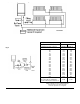
Installation Requirements - Page 10 Safety Valve Setting (bar) Initial System Pressure (bar) Fig 6 Total Water Content of System litres 25 50 75 100 125 150 175 200 225 250 275 300 325 350 375 400 425 450 475 500 For system volumes other than those given above, multiply the system volume by the factor across 3.0 1.0 1.5 VESSEL VOLUME (L) litres 2.7 5.4 8.2 10.9 13.6 16.3 19.1 21.8 24.5 27.2 30.0 32.7 35.7 38.1 40.9 43.6 46.3 49.0 51.8 54.5 litres 3.9 7.8 11.7 15.6 19.5 23.4 27.3 31.2 35.1 39.0 42.
Installation Requirements - Page 11 • The appliance is fitted with an internal frost thermostat, however this device is purely for the protection of the appliance. If any other part of the central heating system requires frost protection, an external frost thermostat should be fitted. • "Material and Installation Specifications for Domestic Central Heating and Hot Water". Frost Protection • The circulating pump fitted within the appliance should be capable of satisfying most system requirements.
Installation Requirements - Page 12 • Inhibitors When the heating system has been completed, it should be cleaned thoroughly in accordance with BS 7593 (code of practice for Treatment of Water in Domestic Hot Water Central Heating Systems) to prevent foreign matter from entering the boiler. Ideally, it should be flushed before the boiler is connected, and again after the system has been heated and is still warm. BetzDearborn Sentinel X300 or Fernox Superfloc are our recommended cleansers for new systems.
2. Installation - Page 13 • It is MOST IMPORTANT that the appliance is installed in a VERTICAL POSITION, with the flue system passing through the wall or ceiling in a Horizontal or Vertical plane. A minor deviation from the horizontal is acceptable, provided that this results in a downward slope of the flue system away from the combination boiler. 2.1 Unpacking 1. Unpack the cartons and check the contents. 2.
Installation - Page 14 2. Connect the central heating return pipe to the isolating cock identified by a Blue lever. (right hand of the two pipes) Connect the hot water outlet pipe using a 15 mm compression fitting. 3. Note: The cold water supply isolating cock incorporates a water strainer. There is an automatic flow limiting device in the inlet fitting - see Fig. 13. Connect the central heating flow pipe to the isolating cock identified by a Red lever. (left hand of the two pipes) 2.5 3.
Installation - Page 15 2.6 Wiring the Appliance The wiring diagram is located on the inside of the front casing panel. 1. 2. Undo the single retaining screw on the top of the controls panel and allow the panel to swing down. Using PVC insulated cable of not less than 0.75 mm². (24/0.2 mm to BS 6500 Table 16), wire up the panel referring to the termination label. (Fig. 10). 3. 4. Check all wiring and reposition the control panel. Secure with screw provided.
3. Commissioning - Page 16 3.1 Electrical Installation Conduct a preliminary electrical test by checking: for short circuits, fuse failure, incorrect polarity, earth continuity and resistance to earth. 3.2 Gas Installation The whole of the gas installation including the meter, should be inspected and tested for soundness and purged in accordance with the recommendations of BS 6891. Purging air from the gas line may be carried out by loosening the union on the gas service cock and purging.
Commissioning - Page 17 3.3 venting of the bearings be required, sideways pressure should be applied and maintained to the knob until a small amount of water becomes visible. The manual restart knob should now be screwed back to its original position, finger tight. Initial Lighting WARNING: Before operating the appliance, check that the air box covers are correctly fitted. The outer white front case should be left off for the time being.
Commissioning - Page 18 14. Fully open all domestic hot water outlets, vent flexible hose connections to the washing machine and dishwasher. Remove air from the domestic hot water distribution system. If this is not done the internal water flow switch will not function properly. Test for gas soundness around the gas components using leak detector fluid. 15. Check the minimum burner pressure (Table 3) by disconnecting one of the Modulating Coil electrical connections (wire colours Red or Black).
Commissioning - Page 19 3.6 D.H.W Flow Rate The appliance contains an automatic flow regulator supplying a nominal flow rate of 7.6 litres/minute. This flow rate will give a nominal temperature rise of 45°C. 3.7 3.8 • Central Heating 1. 2. Ensure that all external controls such as a timers are switched On and that room thermostat/s are calling for heat. Set the Central Heating switch to Timed (if system fitted with Timer) or Constant.
Commissioning - Page 20 3.9 • • A Frost thermostat is fitted which will bring the appliance on when the local temperature around the appliance falls below 5 °C The appliance will shut down when the temperature of the system water has been raised by approximately 10 °C The appliance is protected provided the mains light is illuminated and the boiler switch is set to On, irrespective of the settings of any external controls.
4. Servicing & Routine Maintenance - Page 21 • To ensure the continued safe and efficient operation of the appliance it is recommended that it is checked and serviced as necessary at regular intervals. The frequency of servicing will depend upon the particular installation conditions and usage but in general, once per year should be adequate. It is the law that all servicing work is carried out by competent persons such as CORGI registered personnel.
Servicing & Routine Maintenance - Page 22 4.1 Remove the White Front Case 1. Remove the two securing screws located at the base of the white front case assembly. 2. 3. 4.2 1. 2. 4.3 Ease the base of the case forward approximately 50mm and lift to release the panel from the securing hooks at the top of the appliance. Inspect the heat exchanger for any blockage. Deposits of any material should be brushed away using a soft brush. Note: Do not use brushes with metallic bristles. 2.
Servicing & Routine Maintenance - Page 23
Servicing & Routine Maintenance - Page 24 4.8 Remove the Burner - Fig. 15 4.11 Other Components 1. Disconnect the two leads to the electrodes. (Do not pull on the cable). No further servicing is required on any other appliance components. 2. Undo the hexagonal union nut under the burner, taking care not to lose the seal *. Carefully pull the burner forward approximately 3 mm to disengage the rear burner supports, then lift the rear of the burner to an angle greater than 45°.
Servicing & Routine Maintenance - Page 25
5. Replacement of Parts - Page 26 WARNING: Before attempting to remove any component from this appliance, first disconnect the mains electricity supply by removing the plug from the wall socket or by switching off the appliance at the external isolating switch. Note: The appliance stand-by switch must not be used as the means of isolating, as this switch does leave parts of the appliance electrically live.
Replacement of Parts - Page 27 5.1 Central Heating Overheat Thermostat 5.3 Sensor and Ignition Electrode Fig. 17 1. Remove the white front case and three air box covers. See 4.1 & 4.3 in ‘Routine Maintenance’. 2. The thermostat is located on the outlet tail on the right hand side of the heat exchanger. Disconnect the two electrical leads. 3. Undo the two long fixing nuts and remove the thermostat from the heat exchanger. 4.
Replacement of Parts - Page 28 5.7 1. 2. 3. 4. 5. 6. 7. 8. 9. 5.8 1. 2. 3. 4. 5. 6. 7. 8. 9. 5.9 1. 2. 3. 4. 5. Gas Valve - Fig. 18 Remove the white front case, base panel & white left hand side panel. See 4.1, 4.2 & 4.3 in ’Routine Maintenance’. Isolate the gas supply at the gas cock (1/4 turn). Remove the electrical connectors from the modulating valve, the plug from the first solenoid valve and gas valve compensation tube. Undo the nut on the lower gas supply tube.
Replacement of Parts - Page 29 Fig 18
Replacement of Parts - Page 30 Fig 19 5.12 1. 2. 3. 4. 5. Central Heating and Boiler Switches Remove the white front case and base panel. See 4.1 & 4.2 in ‘Routine Maintenance’. Lower the facia panel, (1 screw). Make note of the wire routing and switch orientation and disconnect the molex plug from the electronic control board. Using a small screwdriver press the retaining lugs on the switch body sides inwards and remove the switch from the control panel.
Replacement of Parts - Page 31 5.14 1. Air Pressure Switch - Fig. 11 & 20 5.15 Remove the white front case, base panel and white right hand side panel. See 4.1, 4.2 & 4.3 in 'Routine Maintenance'. From the top right hand side of the boiler undo the securing screw retaining the pressure switch /bracket assembly Lift the pressure switch / bracket assembly clear of the top of the boiler. Note positions and disconnect pressure tubes and electrical connectors.
Replacement of Parts - Page 32 5.19 1. 2. 3. 4. 5. 6. 7. Remove the white front case and base panel. See 4.1 & 4.2in ’Routine Maintenance’. Lower the control panel assembly by undoing the securing screw at the top right hand side of the control panel. Close the 15mm cold water isolating valve, open the lowest hot water tap then remove the drain screw from the isolating valve to drain the system. Note the position of the electrical connections and remove the two wires from the micro switch.
Replacement of Parts - Page 33 5.22 Diverter Valve - Fig. 22 The diverter valve is made up in two parts. The wax capsule head forms one part and provides the motive power to open the valve. The second part, the valve consists of the change over mechanism and the valve seating. It is likely that only replacement of the head will be necessary, if the complete valve requires replacement proceed to (ii). (i) Wax Capsule Head 1. 2. 3. 4. 5. 6. 7. Remove the white front case and base panel. See 4.1 & 4.
Replacement of Parts - Page 34 5.23 Expansion Vessel C.H. In the unlikely event of a failure of the C.H. expansion vessel it is recommended that a new vessel be fitted exterior to the boiler. It should be positioned on the C.H. Return pipe (see Fig. 6) as close to the boiler as possible. If however, the vessel must be replaced then the following procedures may by used.
Replacement of Parts - Page 35 5.24 Expansion Vessel D.H.W. - Fig. 23 Isolate the electrical supply prior to this operation. 1. 2. 3. Remove the white front case and base panel. See 4.1 & 4.2in ’Routine Maintenance’. Lower the control panel assembly by undoing the securing screw at the top right hand side of the control panel. Close the isolating valve on the cold water inlet and open the lowest hot water tap. Remove the drain screw on the isolating valve to completely drain the appliance.
Replacement of Parts - Page 36 5.26 1. 2. 3. 4. Remove the white front case, base panel and white left hand side panel. See 4.1, 4.2 & 4.3 in 'Routine Maintenance'. Drain the central heating circuit as described on Page 26. Using a spanner to prevent the retaining nut from rotating unscrew the auto air vent and remove from the appliance.
Replacement of Parts - Page 37 5.28 1. 2. 3. 4. 5. Remove the white front case and base panel. See 4.1 & 4.2 in ’Routine Maintenance’. Lower the control panel assembly by undoing the securing screw at the top right hand side of the control panel. Remove the transformer wiring loom from the retaining cable ties and unplug the connector to the electronic control board PL 6 (top right hand side of control board). Thread the wiring out of the control panel.
6. Fault Finding - Page 38 Preliminary Actions: a. Set Boiler Switch to Standby. - b. Set Heating switch to ‘OFF’ (Centre) c. Turn OFF all Hot Water Taps - d. Ensure all Isolating Valves at base of appliance are OPEN e. Turn ON EXTERNAL GAS and ELECTRICAL Supplies - f.
7.
Functional Flow - Page 40
Electrical Diagram - Page 41
8. Product Specification - Page 42 Heat Input: Heat Output: Gas Rate Max. Range Rate (C.H. Only) Min. Max. Range Rate (C.H. Only) Min. Full 30.0 kW(102,350 Btu/h) 22.5 kW(76,760 Btu/h) 14.4 kW(49,130 Btu/h) 24.0 kW(81,880 Btu/h) 17.2 kW(58,680 Btu/h) 10.4 kW(35,480 Btu/h) 2.86 m³/hr 101 ft³/hr Inlet Pressure Burner Pressure Max. (Max. Setting on Gas Valve) Range Rate (C.H.
9.
Optional Extras - Page 44
Optional Extras - Page 45
10.
Short List of Spares - Page 47 Item Description Qty 1 2 3 4 5 6 7 8 9 10 11 12 13 14 15 16 17 18 19 20 21 22 23 Modulation Control Board Display Board Full Sequence Control Board Pump Kit (Myson Compact) Main Burner Assembly Transformer c/w Wiring Electrode Kit Pressure Relief Valve - 3 bar c/w 'O' Ring Gas Valve - SIT Pressure Gauge Burner Injector, Bray 2.46mm Air Flow Switch - Honeywell C6065A1093 Diverter Valve Assembly Complete Wax Capsule Assembly D.H.W.