October 2011 AMBIflo Installation Manual Working towards a cleaner future
Table of contents 1. 1.1 1.2 1.3 1.4 About this manual Content of this manual Overview table Symbols used Who is this manual intended for? 4 4 4 4 5 2. 2.1 2.2 2.3 2.4 2.5 Safety Appropriate use General safety notes Regulations and standards CE labelling Conformity statement 6 6 6 6 7 8 3. 3.1 3.2 Technical information AMBIFLO dimensions and connections AMBIFLO technical data 10 Loss of pressure AMBIFLO 07-16 circuit diagram AMBIFLO 20 circuit diagram 14 9 9 3.3 3.4 3.5 11 12 4. 4.1 4.2 4.3 4.
9. 9.1 9.2 9.3 9.4 Programming Programming procedure Adjusting parameters Table of settings Explanations of the parameter list 10. 10.1 10.2 10.3 Maintenance Maintenance work Contact protection Faults 3 39 39 39 41 63 109 109 109 109 369622 09.
1. About this manual Please read these instructions carefully before operating the device! 1.1 Content of this manual This manual deals with the installation of AMBIflo air to water heat pumps. The air/water operating mode may be used. An overview of the various documentation for this appliance may be found below. Please store all documents at the installation site of the heat pump! 1.
About this manual Note/Suggestion: You will find background information and useful hints here. Reference to additional information in other documentation 1.4 For who is this manual intended? This installation manual is intended for the person installing the AMBIflo unit into a heating system. Safety 2. Safety Danger! Please ensure that you observe the following safety instructions. 2.
The accessories used must be in accordance with the technical regulations and must be approved by the manufacturer for the specific device. Only original spares may be used. Customers are not permitted to undertake conversions or adjustments of the device, as this will endanger lives and may result in damage to the device. The warranty will become invalid should this guidance not be adhered too.
Safety - Regulations of local energy supply companies Notification requirement (or approval ordinance) ATV data sheet M251 of the Waste Water Association 2.4 CE Marking CE marking means that all guidelines according to the CE standards have been adhered to in the design and manufacture of the AMBIflo unit (see conformity statement). Adherence to the safety requirements according to Guideline 89/336/EWG can only be guaranteed if the heat pump is operated as intended.
Safety 2.
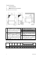
Technical information 3. Technical information 3.1 AMBIflo dimensions and connections Fig. 1: Dimensions and connections 1 2 3 Heating flow Ø 1" (AMBIFLO 16), Ø 1¼" (AMBIFLO 20) flexible. The hydraulic and electrical connections can all be located on the left or right hand side of the heat pump. Heating flow Ø1" (AMBIFLO 16), Ø 1¼" (AMBIFLO 20) flexible 9. A minimum distance of 800 mm must be maintained at the front of the heat pump for maintenance purposes.
Technical information 3.2 AMBIflo technical data Model Heating system Heat output Power consumption COP Condenser Maximum power consumption Starting current with smooth starter Power intensity with locked rotor (LRA) Power connection 1) Fuse (inert) Max speed:fan/Q-pump (Prog.No.3010) 2) Smooth starter settings Water/heat exchanger Hydraulic connections Water content, incl.
Technical information 3.3 Loss of pressure Fig. 2: AMBIflo pressure loss Loss of pressure: water/heat exchanger Loss of pressure [kPa] Flow [l/h] 11 369622 09.
Technical information 3.
Technical information Power plant lock: contact open = power plant lock active Low-tariff: contact closed = low tariff release Low pressure = shown as pressure-free High pressure = shown without overpressure Please note: Indicator bus should only be wired to 5-pin X30 (Bus BE) if length < 10m; otherwise to 3-pin "FB". 13 369622 09.09 Low tariff Power plant lock Heat pump controller ISR – RVS41.
Technical information x3.
Technical information Power plant lock: contact open = power plant lock active Low-tariff: contact closed = low tariff release Low pressure = shown as pressure-free High pressure = shown without overpressure Please note: Indicator bus should only be wired to 5-pin X30 (Bus BE) if length < 10m; otherwise to 3-pin "FB". 15 369622 09.09 Low tariff Power plant lock Heat pump controller ISR – RVS41.
369622 09.09 Further examples of applications (mixer heating circuits, connection to solar heating system, etc.) may be found in the software and hydraulics manuals. Please note: The heat pump must be protected by a circuit breaker with an allphase switch (not by 3 individual fuses)!! The diagram on the right must be used. Local regulations must be observed.
Technical information Prior to installation 4. Prior to installation 4.1 Transport Upon delivery of the heat pump, it must be checked for transport damage and complete delivery according to the order confirmation. Where material is damaged or missing, the transport company must be immediately notified in writing. Care must be exercised during transport, set-up and preparation or when handling the unit so as not to cause damage.
Prior to installation The AMBIflo heat pump is very quiet in operation, however, in the knowledge that noise perception is very subjective, the pump should not be set up near a window, bedroom or leisure site (terrace, swimming pool deck, etc.). A sufficient distance to the adjoining properties should be observed. It is not recommended to set up the pump in a wall niche (possible echo or air blockage).
4.3 Outdoor installation Base The base should project approx 50 mm beyond all sides of the heat pump and be sufficiently high enough to account for snow and water ingress. Prior to installation Fig. 3: Dimensions of air inlet 1 2 Heating flow Ø 1" (16), Ø 1¼" (AMBIFLO 20) flexible. The hydraulic and electrical connections can all be located on the left or right of the heat pump. Heating flow Ø1" (16), Ø 1¼" (20) flexible.
Fig 4. Alternative condensation water outlet via drainage shaft is possible. Drainage pipe insulation at least 3 cm. Minimum size of drainage shaft H = 50 cm W = 50 cm D = 50 cm Water-tight empty pipe (plastic) to be installed 800 to 1000 mm below the ground by the customer, at a gradient of 2% towards the building. Only 45° brackets should be used. 4.
Prior to installation Optimised defrosting When the outdoor temperature drops below 7°C, frost will form on the air/heat exchanger's evaporator. This will result in the formation of ice and will consequently reduce heat exchange and thus the degree of efficiency of the heat pump. To remove this frost or ice, the evaporator must be defrosted.
Prior to installation Prior to installation 4.5 22 AMBIFLO application example 369622 09.
Prior to installation Fig 7: Connection plan Please note: The heat pump must be protected by a circuit breaker with an all-phase switch (not by 3 individual fuses)!! The diagram on the right must be used. Customer's control panel Local regulations must be observed. AMBIFLO 16B The AMBIFLO16B power supply circuit diagram in the installation instructions must be taken into account.
Assembly 5. Assembly 5.1 Heat pump roof Pre-rolled opening for air/water heat pump installed outdoors There is a pre-rolled opening (1) at the bottom of the pump system, behind the electrical control panel, through which the pipes pass into the ground. Where a heat pump is installed outdoors, we recommend that you use this duct. The heating pipes, the condensate connection and the electrical cables all pass through this opening.
Assembly 5.2 Weather protection grid The two weather protection grids (on the inlet and outlet side) must be fixed to the interior frame of the cover. This can be done with the aid of an Allen key (Size 3) or a battery-driven screw driver. The outlet side may be on the left or right. The outlet grid must be used when the system is installed outdoors. Where the weather protection grid is to installed (outdoor installation), the air sensor (5) must be pulled out of the grid. Fig. 9 25 369622 09.
Installation 6. Installation All transport safety devices must be removed before operation. The regulations and diagrams must be carefully followed. The accessories must be installed by an expert (heating system technician) according to the instructions for installation included. The noise emanating from a heat pump of this type is very low, due to the three-step, sound-absorbing bearings used for the movable components and the sound insulation cover.
Installation Fig. 10 6.2 Accumulator When the heat pump is operated with a buffer storage tank, Andrews Water Heaters accumulators of the Solar series are recommended. 6.
Installation The outdoor temperature sensor is enclosed. See circuit diagram for connection instructions. Cable replacement All electrical cables, with the exception of the main power supply cable, must be replaced with Andrews Water Heaters special cables, where required. Only cables of the type H05VV-F are to be used when replacing the main power supply cable. Contact safety Once the AMBIFLO has been opened, the cover panels must be replaced, using the appropriate screws, to ensure contact safety.
Installation Fig. 11 Electricity box 1. 2. 3. 4. 5. 6. 7. 29 RVS heat pump control unit Smooth starter and alternating current relay 230V microfuse Electrical contactor 3x400V main power supply Power plant lock / flow monitor Fan connection 369622 09.
Commissioning 7. Commissioning Danger! An accredited heating technician must commission the system! The heating technician will check the leak-tightness of the pipes, the proper function of all control and safety devices and measure the combustion values.
Commissioning Where commissioning is requested without all these conditions being met, Andrews Water Heaters will take no responsibility for any system operating problems. The system is then operated at the user's own risk and responsibility. The following points must be observed or checked: 1. 2. 3. 4. 5. 6. - Hydraulic circuits: Check concurrence with the documentation provided. Check the electrical connections and fuses. Check the terminal allocation at the heat pump control unit.
Commissioning 7.5 Instructing the operator Instruction The operator must be duly instructed in the operation of the heating system and the function of the protective devices. In particular, the following must be pointed out to him: - The state of the cover is to be checked. The fastening of the outer cover is to be checked. To protect the paintwork, no objects should be leaned against or placed on top of the device.
Commissioning 10. Construction to be dried out 11. Functional test Heating system Domestic Hot Water system 12. Programming Time / date Comfort target value for heating circuit ½ Nominal target value for Domestic Hot Water Automatic daily time program 13. Leak-tightness tested during operation? 14. Operator instructed? 15. Documents handed over? All components used have been checked and labelled in accordance signature with the relevant standards.
Boiler Temperature Operation 8. Operation 8.1 Operating elements Fig. 12: Operating elements 1. 2. 3. 4. 5. 6. 7. 8. 9. 34 Operating mode button for Domestic Hot Water system Control unit Operating mode button for heating system Display OK button (acknowledgement) Information button Turning button ESC button (termination) No function 369622 09.
Operation 8.2 Indicators Fig. 13: Display symbols Meaning of the symbols shown Maintenance message Heating to comfort target value Heating to reduced target value Heating to frost protection target value Current process Holiday function active Error message INFO Information level active PROG Settings level active ECO Reference to heating circuit 1 or 2 8.
Operation - Heating operation without timer program Protection functions active Summer/winter automatic switch not active during permanent operation with comfort target value Automatic daily heat limit switch not active during permanent operation with comfort target value.
Operation Step 1 8.8 Function Calling up further information on the error message (see Error Code Table). Maintenance messages When the maintenance symbol appears on the display, there is either a maintenance message or the system is in special operating mode. Further information can be called up by pressing the information button (see Maintenance Code Table). Step 1 Function Calling up further information on the maintenance message (see Maintenance Code Table).
Operation Step 4 Function Selecting the "On" parameter. 5 38 Heating circuit operating mode button Quitting the programming mode. 369622 09.
Programming 9. Programming Programming must take place after installation. 9.1 Programming procedure The selection of the setting levels and menu points for end users and heating technicians is to be carried out in accordance with the following diagram: Fig. 14: Selection of the setting levels and menu points Basic display Press Press the information button for approx. 3 seconds until the words "End User" appear on the display Setting levels: End user (E) Commissioning (I) incl.
Programming Status of Heat Pump Off Basic display Press Time and datexxxxx Operating unit Use to select the "Time and date" menu point. Confirm selection with to select the "Hours / Minutes" menu point. Use Confirm selection with to set the hours (e.g. 15h00) Use Confirm selection with Use Time and date Hours / minutes Time and date Hours / minutes to set the minutes (e.g. 30 minutes) Time and date Hours / minutes Confirm selection with Time and date Hours / minutes 40 369622 09.
Programming Press heating circuit operating mode button to return to the basic display Status of Heat Pump Off By pressing the ESC button, you can return to the previous menu point without adopting previously changed values. If no new settings are entered within a period of 10 minutes, the basic display will automatically be called up, without any previously changed values being adopted. 9.3 Table of settings - Not all the parameters shown on the display are given in the settings table.
Programming Function Prog. No. 42 Setting 1) level I Operation of heating circuit 2 Jointly with heating circuit 1 / Independently 44 I Jointly with heating circuit 1 Operation of heating circuit P Jointly with heating circuit 1 / Independently 46 I Jointly with heating circuit 1 Effect of presence button None / heating circuit 1 / heating circuit 2 / Jointly 48 I None 54 F 0.
Programming Function rd 3 phase on rd 3 phase off Standard values No / Yes Timer program 4 / Domestic Hot Water system Presetting Mon – Sun Mon-Sun / Mon-Fri / Sat-Sun / Mon / Tue / Wed / Thu / Fri / Sat / Sun st 1 phase on st 1 phase off nd 2 phase on nd 2 phase off rd 3 phase on rd 3 phase off Standard values No / Yes Timer program 5 Presetting Mon – Sun Mon-Sun / Mon-Fri / Sat-Sun / Mon / Tue / Wed / Thu / Fri / Sat / Sun st 1 phase on st 1 phase off nd 2 phase on nd 2 phase off rd 3 phase on rd 3 phase
Programming Function Heating circuit 1 Comfort target value Reduced target value Frost protection target value Reference line for gradient Reference line for shift Reference line for adaptation Off / On Summer / winter heating limit Daily heating limit Minimum feed target value Maximum feed target value Room influence Indoor temperature limit Rapid heat increase Rapid heat reduction Off / To target value for reduction / to target value for frost protection Maximum optimisation for switch-on Maximum optimisa
Programming Function Comfort target value Reduced target value Frost protection target value Reference line for gradient Reference line for shift Reference line for adaptation Off / On Summer / winter heating limit Daily heating limit Minimum feed target value Maximum feed target value Room influence Indoor temperature limit Rapid heat increase Rapid heat reduction Off / To target value for reduction / to target value for frost protection Maximum optimisation for switch-on Maximum optimisation for switch-of
Programming Function Operating mode Safety mode / automatic / reduced / comfort Comfort target value Reduced target value Frost protection target value Reference line for gradient Reference line for shift Reference line for adaptation Off / On Summer / winter heating limit Daily heating limit Minimum feed target value Maximum feed target value Room influence Indoor temperature limit Rapid heat increase Rapid heat reduction Off / To target value for reduction / to target value for frost protection Maximum op
Programming Function Charging process Absolute/Sliding/None/MK sliding, PK absolute Legionnella function Off / periodic / weekday fixer Legionella effect periodic Legionella effect weekday Mon/Tue/Wed/Thu/Fri/Sat/Sun Legionella function time Legionella function target value Legionella function period Legionella effect circulation pump Off / On Circulation pump release Timer program 3/heating circuit P/Domestic Hot Water release/timer program 4/Domestic Hot Water system Circulation pump fixed-cycle operation
Programming Function H3 cooling requirement No / yes Swimming pool Target value for solar heating Target value for generator heating Solar charging priority No / yes With solar incorporation No / yes Preliminary control unit / feeder pump Precontrol / feeder pump In front of buffer tank / after buffer tank Heat pump Condensation pump controls Temp. requirem.
Programming Function Cascade Release integral for generator sequence Reset integral for generator sequence Turn-on delay Automatic change in generator sequence Automatic exclusion of generator sequence None / first / last / first and last Additional generator Release when below outdoor temperature Release when above outdoor temperature Trailing time Switch integral Switch difference off Locking time Solar Temperature difference ON Temperature difference OFF Min. charging temp.
Programming Function Automatic generator lock None / with B4 / with B4 and B42/B41 Automatic generator lock SD Temperature difference between buffer and heating circuit Coating protection Off / permanent Maximum charging temperature Recooling temperature Recooling of Domestic Hot Water / heating circuits Off / on Recooling of collector Off / summer / permanent Charging sensor for electrical insert With B4 / with B42/B41 Forced charging – electrical No / yes With solar integration No / yes Domestic Hot Water
Programming Function Comparative temperature switch-over Domestic Hot Water sensor B3 / Domestic Hot Water sensor B31 Configuration Presetting Heating circuit 1 Off / on Use of mixer 1 None / heating / cooling / heating and cooling Heating circuit 2 Off / on Domestic Hot Water actuator Q3 None / feeder pump / by-pass valve Domestic Hot Water separator switch Off / on Heat source Salt solution / water / air Heating circuit range at TA -10°C Solar actuator Feeder pump / by-pass valve External solar exchanger
Programming Function Function value for contact H1 Voltage value 1 H1 Function value 1 H1 Voltage value 2 H1 Function value 2 H1 Function input H3 Parameter, see function input H1 (Prog. No.
Programming Function Sensor input BX21 None / buffer tank sensor B4 / buffer tank sensor B41 / collector sensor B6 / Domestic Hot Water sensor B31 / cooling agent sensor liquid B83 / domestic hot water circulation sensor B39 / swimming pool sensor B13 / solar feed sensor B63 / solar reflux sensor B64 / buffer tank sensor B42 / section feed sensor B10 / cascade reflux sensor B70 / special temperature sensor 1 / special temperature sensor 2 / Domestic Hot Water sensor B3 / hot gas sensor B81 Sensor input BX22
Programming Function Device address Segment address Bus feed function Off / automatic Bus feed status Off / on Summer switch-over Local / central Operating mode switch-over Local / central Domestic Hot Water allocation Local heating circuits / all heating circuits in segment / all heating circuits in system TA limit for external generator taken into account No / yes Clock operation Autonomous / slave without remote setting / slave with remote setting / master Outdoor temperature - supplier Errors Reset alar
Programming Function Error code for error history 9 Time stamp for error history 10 Error code for error history 10 Errors Reset alarm relay No / yes Reset heat pump No / yes Feed temperature 1 alarm Feed temperature 2 alarm Domestic Hot Water charge alarm Feed temperature cooling 1 alarm Time stamp for error history 1 Error code for error history 1 Time stamp for error history 2 Error code for error history 2 Time stamp for error history 3 Error code for error history 3 Time stamp for error history 4 Error
Programming Function Act Range Evaporator Max / Week Range Evaporator Min / Week Act Range Evaporator Min / Week Domestic Hot Water Tank Time Interval Domestic Hot Water Tank Since Service Domestic Hot Water Tank Feed Temp Heat Pump Minimum Act Domestic Hot Water Feed Temperature Heat Pump Eco-function Locked / released Eco operation Off / on Emergency operation Off / on Emergency operation for function start Manual / Automatic Simulation of outdoor temperature Trigger defrost No / yes Input/output test Rel
Programming Function Voltage signal H3 Contact state H3 Open / closed Input EX1 0 V / 230 V Input EX2 0 V / 230 V Input EX3 0 V / 230 V Input EX4 0 V / 230 V Input EX5 0 V / 230 V Input EX6 0 V / 230 V Input EX7 0 V / 230 V Status Status of heating circuit 1 Status of heating circuit 2 Status of heating circuit P Status of Domestic Hot Water Status of cooling circuit 1 Status of heat pump Status of solar pump Status of buffer tank Status of swimming pool Status of additional generator Time stamp for status
Programming Function Time stamp for status history 9 Status code for status history 10 Time stamp for status history 10 Status code for status history 10 Cascade diagnosis Priority / status of generator 1 Missing / faulty / manual operation active / Generator lock active /chimney-sweep function active/Domestic Hot Water system separation switch active / outdoor temperature limit active / not released / released Priority / status of generator 2 Parameter, see priority/status (Prog.No.
Programming Function Cascade reflux temperature Cascade reflux target value Current generator sequence switch Generator diagnosis Compressor 1 K1 Off / on Electrical insert 1 – feeder Off / on Electrical insert 2 – feeder Off / on Source buffer Q8 / fan K19 Off / on Speed of source pump Condenser pump Q9 Off / on Reflux temperature for heat pump Target value for heat pump Feed temperature for heat pump Hot gas temperature 1 Hot gas temperature max Cooling agent temperature – liquid Temperature range for con
Programming Function Remaining time for defrost locking Remaining time for forced defrosting Number of defrosting attempts Defrosting status heat pump off, TA defrosting release off/ locked/ monitor ice /preheat for defrosting/ defrosting active/drain/cool down evaporator/fault/forced defrosting/defrosting stabilisation/defrosting with fan/ defrosting with compressor /forced defrosting of fan /forced defrosting of compressor Speed of collector pump 1 Speed of solar pump ext.
Programming Function Lead time target value 1 Cooling circuit pump Q24 Cooling circuit mixer open Y23 Cooling circuit mixer closed Y24 By-pass valve cooling Y21 Lead time temperature cooling 1 Lead time target value cooling 1 Heating circuit pump Q6 Off / on Heating circuit mixer open Y5 Off / on Heating circuit mixer closed Y6 Off / on Room temperature 2 Room target value 2 Lead time temperature 2 Lead time target value 2 Room temperature P Room target value P Lead time target value P Domestic Hot Water pu
Programming Function Start counter for electrical buffer Lead time target value H1 Lead time target value H2 Lead time target value H3 Water pressure H1 Water pressure H2 Water pressure H3 Relay output QX1 Off / on Relay output QX2 Off / on Relay output QX3 Off / on Relay output QX4 Off / on Relay output QX5 Off / on Relay output QX6 Off / on Relay output QX7 Off / on Relay output QX8 Off / on Relay output QX21 Module 1 Off / on Relay output QX22 Module 2 Off / on Relay output QX22 Module 3 Off / on Relay o
Programming Status of buffer tank Status of Domestic Hot Water Status of swimming pool Status of heating circuit 1 Status of cooling circuit 1 Status of heating circuit 2 Status of heating circuit P 1) E = end user, I = maintenance, F = technical expert Parameters with the program numbers (Prog. No.) 1 to 54 are individual parameters of the operating unit and the indoor system and can therefore be set independently on both devices. All parameters from Prog. No.
Programming Save basic settings of to operating unit (30) Activate basic settings of operating unit (31) Use as (40) Allocation Indoor Unit 1 (42) Operation heating circuit 2/heating circuit P (44, 46) Effect of preference button (48) Correction of indoor sensor (54) Device version (70) 64 The control parameters are written to / saved in the indoor system (only available for the indoor system) Caution! The parameters of the indoor unit are overwritten! This makes it possible to save the individual prog
Programming The Timer Program 3 can be used for the Heating Circuit P, the domestic hot water and the circulation pump, depending on the setting. It is always displayed. Preselection (500, 520, 540, 560) The Timer Program 4 can be used for domestic hot water and for the circulation pump, depending on the setting. It is always displayed. Selection of week days or week blocks. The week blocks (Mo-Su, Mo-Fr and Sa-Su) are setting aids.
Programming Operating mode (1300) Comfort target value (710, 1010, 1310) Reduced target value (712, 1012, 1312) Frost protection value (714, 1014, 1314) Maximum comfort target value (716, 1016, 1316) Characteristic incline (720, 1020, 1320) 66 Heating circuits This Prog. No. can be used to select the operating mode for the Pump Circuit P. The operating mode for Heating Circuits 1 and 2 is directly set on the operating unit. Sets the comfort target value.
Programming Feed temperature Figure 15: Heating characteristic diagram Outside temperature Shift of characteristic (721, 1021, 1321) Adaptation of characteristic (726, 1026, 1326) Summer / winter heating limit (730, 1030, 1330) 67 Correction of the heating characteristic by parallel shift when the inside temperature is generally too high or too low. Automatic adaptation of the heating characteristic to the current situation, which obviates a correction of the heating characteristic incline.
Programming Figure 16: Summer / winter heating limit Attenuated outside temperature (Prog. No.
Programming Indoor effect (750, 1050, 1350) The feed temperature is calculated as a function of the outside temperature using the heating curve. This control type assumes that the heating characteristic is set correctly, because with this setting, the controller does not make use of the indoor temperature.
Programming Fast heating-up (770, 1070, 1370) The fast-heating-up function becomes active when the indoor target value switches from protection level or reduced level to comfort level. During fast-heating-up function, the indoor target value is increased by the value set here. The actual indoor temperature increases to the new threshold in a relatively short period, due to this setting.
Programming -10 °C 0 0.4 1 2.1 3.1 4.1 10.3 -15 °C 0 0.4 0.9 1.8 2.6 3.5 8.8 -20 °C 0 0.3 0.8 1.5 2.3 3.1 7.7 Duration of the fast-lowering function when lowering by 4 °C, in hours: Building time constant (configuration, Prog. No. 6110) Mixed outside temperature 0h 2h 5h 10 h 15 h 20 h 50 h 15 °C 0 9.7 24.1 10 °C 0 3.1 7.7 15.3 23 5 °C 0 1.9 4.7 9.3 14 18.6 0 °C 0 1.3 3.3 6.7 10 13.4 -05 °C 0 1 2.6 5.2 7.8 10.5 26.2 -10 °C 0 0.9 2.1 4.3 6.4 8.6 21.5 -15 °C 0 0.7 1.8 3.6 5.5 7.3 18.2 -20 °C 0 0.6 1.6 3.2 4.
Programming Reduced-increase start (800, 1100, 1400) Reduced-increase end (801, 1101, 1401) When little heating power is required, the reduced indoor target value at cold outside temperatures can be increased. The increase depends on the outside temperature. The lower the outside temperature, the more the reduced target value for the indoor temperature is increased. The start of the increase and the end point can be set.
Programming Screed function (850, 1150, 1450) The screed function is used for controlled drying of screed screeds. - Off: The function is switched off. - Function heating (Fh): Part 1 of the temperature profile is automatically executed. - Covering-readiness heating (Bh): Part 2 of the temperature profile is automatically executed. - Function and covering-readiness heating: The whole temperature profile is automatically executed. - Manual: The screed target value is manually maintained.
Programming Over-temperature reduction (861, 1161, 1461) With buffer storage unit (870, 1170, 1470) With preregulator / feed pump (872, 1172, 1472, 5092) Operating mode switching (900, 1200, 1500) Nominal target value (1610) Reduced target value (1612) Release (1620) 74 Surplus heat can be reduced by generating less heat in the indoor heating system when the over-temperature reduction is activated on Input H1 or H3 or when the maximum temperature in the system is exceeded.
Programming Figure 22: Release as a function of the timer switching programs of the heating circuits (example) - Timer Program 4: The Domestic Hot Water temperature is switched between the Domestic Hot Water temperature target value and the Domestic Hot Water temperature reduced target value, independently of the timer switching programs of the heating circuits. The Timer Switching Program 4 is used for this purpose (see Figure 23).
Programming Legionella function, week day (1642) Legionella function, fixed time (1644) Legionella function target value (1645) Legionella function period (1646) Legionella function circulation pump (1647) Circulation pump release (1660) Circulation pump cycle mode (1661) Circulation pump target value (1663) H1/H2/H3 Domestic Hot Water system feed process (2008, 2033, 2044) H1/H2/H3 overtemperature reduction (2010, 2035, 2046) H1/H2/H3 with buffer tank (2012, 2037, 2048) 76 Sets the weekday for the fi
Programming H1/H2/H3 preregulator/ feed pump (2014, 2039, 2050) Target value solar heating (2055) Target value generator heating (2056) Charging priority solar (2065) With solar integration (2080) Preregulator/feed pump (2050) Control condenser pump (2801) Lead time condenser pump (2802) Trailing time condenser pump (2803) Lead time source (2819) Determines whether the heating circuit is supplied from the preregulator / with a feed pump.
Programming Trailing time source (2820) Switching difference reflux pump (2840) After the compressor has been switched off, the source pump/fan continues running for the trailing time set. For systems without buffer or combined tank When the reflux temperature exceeds the target value by half a switching difference, the controller requests the operation of the heat pump.
Programming Release of electrical feed below TA (2884) The electrical unit is only released when the damped outside temperature (TA) is below the temperature set here. Compensation heat deficit (2886) This function compensates for heat surpluses and deficits.
Programming Evaporator temperature defrostend (2954) Time to forced defrosting (2963) Defrosting period, max (2964) Dripping-off period evaporator (2965) Cooling-down period evaporator (2966) During compressor operation (3006) Max.
Programming Automatic generator sequence exclusion (3541) Release below/above outside temperature (3700/ 3701) - None: After expiry of the time set in Prog. No. 3540, the boiler sequence is changed. - First: The boiler with the first address works as main boiler. The order of all the other boilers is changed after the time set in Prog. No. 3540 has expired. - Last: The boiler with the last address always remains the last boiler.
Programming Charging temperature min. Domestic Hot Water system storage tank (3812) The storage tank charging process requires that a specific collector temperature is reached, in addition to the temperature difference. Figure 24: Charging controller (dT) SdON SdOFF On Off Charging temperature min. buffer tank (3815) Charging temperature min.
Programming Charging time relative priority (3825) Waiting time relative priority (3826) Waiting time parallel operation (3827) Delay secondary pump (3828) Collector start function (3830) Minimum operating time collector pump (3851) Collector start function gradient (3834) Collector frost protection (3840) Collector overheating protection (3850) Evaporation heat transfer fluid (3860) Pump rotation speed limitations (3870, 3871) Frost protection agent (3880) Frost protection agent concentration (3881) 83
Programming Pump flow (3884) Forced charging for heating min/max (4709/ 4710) Forced charging target value heating max. (4710) Forced charging time (4711) Forced charging duration max (4712) Automatic generator lock (4720) Automatic generator lock SD (4721) Temperature difference buffer/heating circuit (4722) 84 Enter the flow of the built-in pump to calculate the pumped volume for the yield measurement.
Programming Layer protection (4739) The buffer layer protection function facilitates a hydraulic balance between the consumers and the generator without additional stop valves to the buffer tank. When the function is active, the water volume at the consumer side is adapted to ensure that as little cold water as possible is mixed in from the buffer tank. This function requires that a section feed sensor B10 is connected.
Programming Transfer excess (5021) Charging type (5022) Charging temperature maximum (5050) Cool-down temperature (5055) Cool-down boiler/heating circuit Cool-down collector (5057) Electrical unit operating mode (5060) Electrical unit release (5061) Electrical unit control (5062) 86 Energy from the buffer tank can be transferred to the Domestic Hot Water tank. This requires, that the current buffer tank temperature is higher than the current temperature in the Domestic Hot Water tank.
Programming Over-temperature reduction (5085) With buffer tank (5090) With preregulator/feed pump (5092) With solar contribution (5093) Transfer strategy (5130) Reference temperature transfer (5131) Over-temperature reduction can be initiated by the following functions: Storage tank temperature maximum, automatic push, charging preference time push, over-temperature reduction, active inputs H1, H2 H3 or EX2, cooling-down of storage tank, solid boiler overtemperature reduction.
Programming Domestic Hot Water separating circuit (5736) The Domestic Hot Water separating circuit can only be used with a boiler cascade. - Off: The Domestic Hot Water separating circuit is switched off. Any boiler can supply the Domestic Hot Water tank. - On: The Domestic Hot Water separating circuit is switched on. The Domestic Hot Water is only provided by the boiler specified.
Programming External solar heat exchanger (5841) Combination storage tank (5870) Relay outputs QX1/ QX2/ QX3/ QX4/ QX5/ QX6 (5890-5896) - Jointly: Use the solar heat exchanger for the Domestic Hot Water and buffer tank. - Domestic Hot Water tank: Use the solar heat exchanger for the Domestic Hot Water tank. - Buffer tank: Use the solar heat exchange for the buffer tank. This setting activates functions that are specific for the combination storage tank.
Programming - Solar actuator buffer K8: When several heat exchangers are connected, the buffer tank must be selected at the appropriate relay output and the type of the solar actuator must be defined with Prog. No. 5840. - Solar actuator swimming pool K18: When several heat exchangers are connected, the swimming pool must be selected at the appropriate relay output and the type of the solar actuator must be defined with Prog. No. 5840.
Programming Function Input H1/H2/H3 (5950, 5960, 6046) - Operating mode switching heating circuits and Domestic Hot Water system: Switches the operating mode of the heating circuits to reduced mode or protection mode (Prog. No. 900, 1200, 1500) and locking of Domestic Hot Water charging when the contact H1/H2/H3 is closed. - Operating mode switching heating circuit 1 or KKP: Switches the operating mode of the heating circuits to protective mode or reduced mode.
Programming Effect contact H1/H3/H2 (5951, 5961, 6047) Voltage Value 1 H1/H3/H2 (5953, 5963, 6049) Function Value 1 H1/H2/H2 (5954, 5964, 6050) Voltage Value 2 H1/H3/H2 (5955, 5965, 6051) Function Value 2 H1/H2/H2 (5956, 5966, 6052) Function Input EX1-4 (5980-5984) - Release swimming pool: Activation triggers charging the swimming pool by the heat generator.
Programming After expiry of the "Minimum standstill period", the heat pump is restarted. When the flow monitor is again triggered during the "Duration fault repeat", the heat pump is switched to fault mode and can only be re-operated after unlocking. - Flow monitor source E15: Accepts the signal of a flow monitor of the source.
Programming Sensor input BX21/BX22 (6040, 6041) Signal logic output UX (6071) Temperature value 10 V UX (6075) Sensor type collector (6097) Correction of collector sensor 1 (6098) Time constant building (6110) System frost protection (6120) 94 The configuration of the sensor inputs BX21 and BX22 allows more functions in addition to the basic functions; - None: Sensor inputs BX21/BX22 deactivated.
Programming Store sensors (6200) Delete sensor (6201) Control numbers generator 1 / storage tank / heating circuit (6212, 6213, 6215, 6217) The sensor states can be stored with Prog. No. 6200. This happens automatically. When the system is changed (removal of a sensor), the status of the sensor terminals must be newly saved. This setting deletes all sensors connected. The sensors are newly read with the function "Store sensors" (Prog. No.
Programming 24 25 26 27 Solar X X X X 31 33 35 37 X 38 39 X X X X X X 40 X 41 42 44 X X 45 46 48 X X X 49 50 X X X X X X X X 51 X X 52 X X Domestic Hot Water system Domestic Hot Water system P P * Domestic Hot Water system/P Domestic Hot Water system+P Domestic Hot Water system/P Domestic Hot Water system Domestic Hot Water system P Domestic Hot Water system/P Domestic Hot Water system/P Domestic Hot Water system+P Domestic Hot Water system/P Domestic Hot Water system Domestic H
Programming 51 60 61 Heat pump Air/water heat pump, 2 stages, with process reversal valve Heat pump, 1 stage, for external monitoring Heat pump, 2 stages, for external monitoring Table 6: Control number buffer tank (Prog. No.
Programming Heating circuit P Software version (6220) Device address/segment address (6220) Bus feed function (6604) Bus feed status (6605) Summer switching (6621) Operating mode switching (6623) Domestic Hot Water allocation (6625) Heating circuit P 2027 3038 4042 Heating circuit 1 Heating/cooling, 2-wire, separate distribution Heating/cooling, 4-wire, separate distribution Only cooling, 4-wire Displays the current software version LPB system The two-segment LPB address of the controller consists of
Programming TA limit ext generator taken into account (6693) Additional generators connected via the LPB bus can be locked or released according to their own parameters, based on the external temperature (e.g. air/ water heat pump). This status is distributed via LPB. In a cascade, the master thus knows whether an additional generator (slave) is available according to the capacity limits (outdoor temperature) or not and can add another generator accordingly.
Programming Table 8: Error messages No.
Programming Manual acknowledgement No No No Heat pump operation Yes No Yes No Yes B21 E14 LPB LPB LPB E10 No No No No No No No No No No No No Yes Yes ------Yes Yes Yes No No Yes Yes Yes Yes Yes No Yes Yes No No ------No E10 Yes No E10 Yes No E9 E11 E12 B63 B64 B13 B36 Yes Yes Yes No No No Yes No No No No Yes Yes Yes No Yes B38 No Yes H3 H3 No No No No No No No No No Yes No Yes Yes Yes Yes Yes Yes Yes No.
Programming No. Error text 333 334 335 336 339 340 341 343 344 345 350 351 352 353 354 355 BX4 no function BX5 no function BX21 no function BX22 no function Collector pump Q5 missing Collector pump Q16 missing Collector sensor B6 missing Solar integration missing Solar buffer K8 missing Solar swimming pool K18 missing Buffer address error Precontrol/feeder pump address error Hyd.
Programming Range Condens Mx/Week (7076) Actual Range Condens Mx/Week (7077) Range Condens Min/Week (7078) Actual Range Condens Min/Week (7079) Range Evaporator Max/Week (7080) Actual Range Evaporator Max/Week (7081) Range Evaporator Min/Week (7082) Actual Range Evaporator Min/Week (7083) Domestic Hot Water Store Time Interval (7090) Domestic Hot Water Store Since Maintenance (7091) Domestic Hot Water Charge.
Programming Actual Domestic Hot Water Charge. Temp. HP (7093) Eco-function (7119 Eco-operation (7120) Emergency Operation (7141) Emergency Operation Function Mode (7142) Simulation Outdoor Temperature (7150) Trigger Defrosting (7152) Input/Output Tests (7700 to 7917) Status Queries (8000 to 8010) The control unit records the Domestic Hot Water temperature at which the heat pump discontinued charging last time, i.e.
Programming End user (information level) Monitor addressed Manual operation active Screed function active Heating operation restricted Forced reduction Comfort heating operation Reduced heating operation Frost protection active Summer operation Off Commissioning, technician Monitor addressed Manual operation active Screed function active Overheating protection active Restricted, boiler protection Restricted, Domestic Hot Water system priority Restricted, buffer Forced reduction – buffer Forced reduction
Programming End user (information level) Charging of electrical insert Push active Charging active Trailing time active Charged, max.
Programming End user (information level) Passive cooling operation Frost protection active Off Commissioning, technician Restriction Range Evaporator Min Compressor 1 and electrical unit on Compressor 1 and 2 on Compressor 1 on Compressor 2 on Passive cooling operation System frost protection active Lead time active Trailing time active Released, evaporator ready No heat requirement The following messages are possible for the solar function: End user (information level) Manual operation active Fault Coll
Programming* End user (information level) Charged Commissioning, technician Charged, max. storage temperature Charged, maximum charging temperature Charged, target temperature for forced charging Charged, target temperature * Partially charged, target temperature Charged, minimum charging temperature Diagnosis for source/consumer (8310 to 8980) Display of various target and actual values and counter static for diagnostic purposes. 108 369622 09.
Maintenance 10. Maintenance Risk of electrocution! The power supply to the device must be switched off before the cover components are removed. Once the cover has been removed, any person working on the device when the power supply has been switched on must be a trained electrician! 10.1 Maintenance work Maintenance of the heat pump must be carried out by specially trained technicians.
Maintenance To ensure optimal operation, we recommend that you take out a maintenance contract. Operating faults displayed by heat pump control unit Errors or operating faults are always handled by the heat pump controller and resetting may take place automatically (automatic reset function). The cause of the fault and the further procedure to be followed are displayed when the information button on the controller operating unit is pressed.
Maintenance Fault removal The error messages displayed as a result of operating faults are described and explained below. Table 9: Fault removal of smooth starter Fault Motor does not start Cause LED OFF LED ON LED flashes 1. Overload 2. Overheat 3. Phase reversal 4. Phase failure, no load 5. Phase asymmetry 6. Short-circuit in thyristor Motor starts, but starting process is terminated before the correct speed has been reached LED ON LED flashes 1. Overload 2. Overheat 3. Phase failure, no load 4.
Maintenance Fault Motor stops unexpectedly and can no longer be started Cause LED ON LED flashes 1. Overload 2. Overheat 3. Phase failure, no load 4. Phase asymmetry 112 Removal, steps to be taken - Check whether the interrupt switch is on. - Check whether the power supply is on. - Reset the device - Triggered by overheating. Wait for the device to cool down. Check the operating time against the data provided in the pump specifications.
Index A Acknowledgement message 37 Air input or output 16 B Barrier - Operation 63 - Programming 63 C Checklist 32 Circulation pumps 27 Commissioning 30 Comfort target value 31 Connecting components 27 Contact protection 28 D Daily heating limit 68 Daily heating limit automation 35 Device version 64 Domestic Hot Water system 36 E ECO 35 Emergency operation 104 Error message 35, 36 Error messages 109 F Factory settings 64 Fault display 63 Frost protection target value 66 G Gravity barrier 109 H Heating ope
Space for notes 114 369622 09.
Space for notes 115 369622 09.
Publication Date: 1011 0087 Baxi Commercial Division Wood Lane, Erdington, Birmingham B24 9QP Sales: Technical: 0845 070 1056 0845 070 1057 Email: andrews@baxicommercialdivision.com www.andrewswaterheaters.co.