
Installation manual

23 369622 09.09
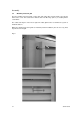
Prior to installation
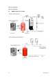
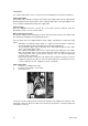
Fig 7: Connection plan
Please note: The heat pump must be protected Customer's control panel
by a circuit breaker with an all-phase switch
(not by 3 individual fuses)!! Fuses according to WP type:
The diagram on the right must be used.
Local regulations must be observed. AMBIFLO 16B 25A,
The AMBIFLO16B power supply circuit diagram Power plant lock:
in the installation instructions must be taken Contact closed for Power
into account. BSW release plant
gate
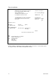
Parameters to be set:
Menu point Function Setting
"I" configuration 5700 Factory setting 1
Only for AMBIFLO6-16A
"I" configuration 5890 QX1 relay output Electrical insert 1
K25 supply
Network
ISR - RVS41.813 heat pump controls
Key:
ATF External temperature sensor QAC34
F10 All-phase circuit breaker 1)
KSP Condenser pump *)
S2 Main switch 1)
*) Accessory
1) Factory setting
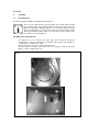
Further examples of applications (mixer heating circuits, connection to solar heating system,
etc.) may be found in the software and hydraulics manuals.