
Installation manual


9 369622 09.09
Technical information
3. Technical information
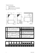
3.1 AMBIflo dimensions and connections
Fig. 1: Dimensions and connections
4 Air inlet (at the back of the device),
For details, see air connections
5 Air outlet (at left, right or top),
6 For details, see under air connections
1 Heating flow
Ø 1" (AMBIFLO 16), Ø 1¼" (AMBIFLO
20) flexible. The hydraulic and electrical
connections can all be located on the left
or right hand side of the heat pump.
7 Internal electrical panel
8 Electrical connections
Adjustable legs, absorbing structure-
borne noise
2 Heating flow
Ø1" (AMBIFLO 16), Ø 1¼" (AMBIFLO 20)
flexible 9. A minimum distance of 800
mm must be maintained at the front of
the heat pump for maintenance
purposes. A minimum distance of 500
mm is required on the free side opposite
the air outlet.
9 A minimum distance of 800 mm must be
maintained at the front of the heat pump
for maintenance purposes. A minimum
distance of 500 mm is required on the
free side opposite the air outlet.
3 Condensation water outlet Ø ¾", flexible
Table 1: Dimensions
Hydraulic connections Width
a
Height
b
Depth
c
Bottom
height
d
Top
height
e
i j k t p
Legs
q
AMBIflo
all dimensions in mm
16
1195 1675 750 575 1060 210 300 390 100 300 40
20
1195 1695 880 670 975 230 385 545 110 300 50