2nd Fix Solar Manual Please read these instructions before installing or commissioning. This Solar Thermal Domestic Hot Water System should only be installed by a competent person. PLEASE LEAVE THESE INSTRUCTIONS WITH THE USER FOR SAFE KEEPING.
Index 2 3 4 5 6 Index Introduction to Solar Hydraulic station specifications Differential temperature controller specifications Ancillary components Expansion vessel Solar heat transfer fluid 7 Cylinder specifications Unvented Cistern-fed vented 9 Safety information 11 Installation of hydraulic station Parts list Identification of components Pipework installation - general Installing the hydraulic station - positioning Installing the wall brackets and hydraulic station Installing the safety group Connecti
1.0 6 1.1 2. The sun is the ultimate source of most of our renewable energy supplies. Energy from the sun is clean and abundant. 2 3 8 11 1 12 5. Solar water heating technology captures energy from the sun and transfers this to a water heater to raise the water temperature therefore reducing the reliance on fossil fuel energies such as gas, oil and electricity. Up to 60% of a dwelling’s annual hot water requirement can be provided by a solar water heating system.
2.0 2.1 Hydraulic station specifications Technical data Dimensions System Module Pump Station Cascade Module Pump Station (Height/Width/Depth) 375/250/190mm 375/190/190mm Flow and return connections (compression fittings) 22mm Maximum working temperature: Maximum working pressure: Pressure Relief Valve setting: Circulating Pump: Circulating Pump voltage: Power consumption Setting 1: Setting 2: Setting 3: Maximum Pump Head: Maximum Pump Capacity: Flow meter scale: Fig. 3 System Module Fig.
3.0 3.1 Fig. 5 Differential temperature controller Technical data Housing Material 100% recyclable ABS Dimensions L x W x D in mm weight 175 x 134 x 56 ca. 360 g Ingress protection IP40 according to VDE 0470 Electrical values Operating voltage 230/240V ~ 50 Hz Interference grade N according to VDE 0875 Max. conductor cross-section 240V-connections 2.
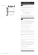
4.0 Ø300mm Expansion vessel 392mm 3/4” 4.1 Ancillary components Expansion vessel 1. Membrane expansion tanks for solar primary heating circuit. Manufactured according to the Directive PED 97/23/CE (approved noZ-DDK-MUC-02-396876-04). 2. Butyl membrane suitable for solar primary heating fluid, DIN 4807-3 approval. Maximum working temperature +110°C. Maximum percentage of glycol 50%. Connection: 3/4” BSP male parallel 3.
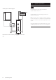
5.0 5.1 Cylinder specifications Unvented Unvented system - schematic diagram Main recommend the use of the Main Solar unvented cylinders. 6 2 4 2 3 8 11 10 12 Note: Indirect twin coil unit shown. 1 Fig. 7 Nominal capacities 210, 250 and 300 litre. Rating Immersion heater(s) 1 x 3 kW (indirect models), 2 x 3kW (direct models) @ 240V~. Outer casing White plastic coated corrosion proofed steel. Thermal insulation CFC/HCFC-free (ODP zero) flameretardant expanded polyurethane (60mm thick). GWP 3.
5.0 Cylinder specifications 5.2 Vented system - schematic diagram For full technical and performance specification see cylinder installation instructions. Detailed installation and commissioning instructions are supplied with the cylinders. Note: The system is also compatible with cylinders configured for solar DHW systems. For installation and specification details refer to the manufacturers instructions supplied with the solar cylinder.
6.0 6.1 Safety Information Safety 1. In order to reduce the number of deaths and major accidents attributable to work at height, the Health and Safety Executive has introduced comprehensive regulations and guidance that should be followed by all businesses working at height. 2. We consider in the following paragraphs some of the main features of the regulations and guidance.
6.0 6.1 Safety Information Safety (cont) Risk Assessments 8. The HSE has published a number of very useful free publications that advise how to undertake risk assessments. 9. Two of these that you should obtain are: Five Steps to Risk Assessment. A Guide to Risk Assessment Requirements. 10. The five steps outlined in the HSE leaflet are: Step 1: Look for the hazards, this will mean looking at the site and identifying significant hazards.
7.0 Installation of hydraulic station Fig. 9 (Diagrams not to scale) 7.1 3 1 Parts list Before commencing the installation check all listed components are contained in the following cartons. Hydraulic Station carton: 2 4 1. Hydraulic pump station with insulation incorporating wall mounting bracket. 2. Solar differential temperature controller. 3. Safety group, comprisingPressure relief valve, pressure gauge and fill & drain valve. 4. 22mm compression fitting nut and olive(4 off). 5.
7.0 7.2 Installation of hydraulic station Identification of components 1. The main components of the hydraulic station are: 1 3 2 4 6 – Two isolating valves (Fig. 10, Item 1 & 2) with integral thermometers which display the solar primary flow and return temperatures. – A safety group (Fig. 10, Item 3, supplied unconnected), which protects the solar primary circuit. The pressure relief valve and pressure gauge are integrated in the safety group.
7.0 Installation of hydraulic station Fig. 11 7.3 See Fig. 11 5 4 3 2 1 8 1 2 3 4 5 6 7 8 9 7.4 7 6 9 Solar cylinder Collector temperature sensor lead Solar primary flow (from collector) Solar collectors Solar primary return (to collector) Solar primary flow (to cylinder) Solar primary return (from cylinder) Solar differential temperature controller Cylinder temperature sensor lead Pipework installation - general 1.
7.0 Installation of hydraulic station Fig. 12 7.4 Pipework installation - general (cont) 8. Venting the pipework The hydraulic station the component includes an air collector/separator and bleed point so an automatic air vent is not necessary. Any section of solar pipework that falls and rises again should be fitted with an additional air vent valve to relieve any trapped air which may cause air locking in the system.
7.0 Installation of hydraulic station Fig. 13 7.5 Installing the hydraulic station - positioning 1. It is usual to install the hydraulic station and solar differential temperature controller near to the solar cylinder. However this does not have to be the case, the hydraulic station can be installed anywhere convenient on the solar primary pipework although adequate access will be necessary for commissioning and maintenance. 2.
Fig. 15 1 3 7.0 7.7 Installation of hydraulic station Installing the safety group 2 1. Connect the safety group (Fig 15 Item 1) to the connection on the hydraulic station return isolating valve assembly (Fig 15 Item 3). Ensure that the pre-fitted gasket is securely in place on the safety group prior to connection. 7.8 Fig. 16 4 5 3 1 2 1.
Fig. 19 8.0 Commissioning of system 3 45° 4 5 8.1 Air Test 1. An air test may be used on the pipework to detect any gross leakage prior to flushing and filling with solar heat transfer fluid. Pressurise the system to a maximum of 1 bar to check for leaks. 1 2. Ensure that the solar expansion vessel pre-charge pressure has been set prior to flushing and filling. 6 2 8.2 7 Read at top of float Fig. 20 Flushing and Filling the pipework 1.
8.0 8.3 Commissioning of system Flushing and Filling the pipework (cont) 11. Pour an amount of the solar heat transfer fluid into the filling pump. 12. Close the fill and drain valve - safety group (Fig. 19 Item 1) and the fill and drain valve - flow meter (Fig. 19 Item 2) and pressurise the pump slightly prior to filling the system. If an electric pump is being used follow the instructions with the pump. 13.
9.0 Installation of solar controller Fig. 22 Hydraulic Station Solar panel sensor Solar differential controller 9.1 Terminal block for extending collector sensor Double pole isolating switch L N E 230V/240V~ Mains supply The collector panel temperature sensor should be installed in the sensor pocket at the collector array flow connector as part of the first fix process. Ensure that the cable from this sensor can be identified for connection to the pump station wiring centre.
9.0 Installation of solar controller Fig. 23 9.3 1. Always disconnect from the mains before opening the controller cover. The electrical installation must conform to all current Wiring Regulations and be carried out by a competent electrician.
Fig. 25 Type 0: 1 collector, 1 storage tank 9.0 9.5 Tc1 Installation of solar controller Solar Gain measurement (Accessories required) Collector Storage tank The controller is capable of measuring solar gain if accessories are fitted to the system, see Fig. 25. Tth *1 Tret *2 P1 Ts1 1. For solar gain (energy productivity) measurement it is necessary to fit the collector return sensor as shown in the diagram in Fig. 25. and input the correct flow value. FM *2 2.
Fig. 26 9.0 Block Wiring Schemes A. In conjunction with auxiliary heating by boiler - no reheat control 9.6 Installation of solar controller Connection of temperature sensors by solar controller.
Fig. 26 9.0 Installation of solar controller 9.8 D. Auxiliary heating by boiler with 3 port mid position valve system - no reheat control by solar controller.
10.0 10.1 Commissioning of hydraulic station Ensure the solar primary system is free from air 1. Switch on the power supply to the solar differential temperature controller. 2. Manually switch the circulation pump ON and OFF via the solar differential temperature controller (see section 11.5) to pump fluid around the solar primary system. 3. Turn the pump off and open the airbleed screw on the air separator (Fig. 27 Item 1). Bleed any air from the air separator.
Fig. 28 Diagram of all possible symbols 11.0 Main Menu On completion of commissioning the Solar Controller, note all the required information in the Solar Commissioning Record Sheet at the end of Section 12. 11.1 1 Sub-Menu Commissioning of solar controller Main Menu To make the operation of the controller clear, operating and display functions are divided into 4 main menus. Info Indication of current measured values. Indication of system condition. Indication of error messages.
Fig. 29 Press or 11.0 to scroll Commissioning of solar controller up or down to the required sub function. The icon will flash, press 11.3 to select the function. Reset by pressing or In this menu mode all measured values and operating states are shown. for increase/decrease values. Press and ok? press If the values are marked as “reset possible”, they may be reset in the following way: appears, to confirm and Menu “Info” Choose the value with buttons ok? disappears.
Fig. 30 Press or to scroll 11.0 Commissioning of solar controller up or down to the required sub function. The icon will flash, press to select the function. Reset by pressing or for increase/decrease values. Press and ok? appears, press to confirm and ok? 11.4 Menu “Programming” 1.All adjustable parameters can be checked in this menu and, if necessary, changed. The default factory setting will usually give efficient and problem free operation. 2.
Fig. 31 Press or to scroll 11.0 Commissioning of solar controller up or down to the required sub function. The icon will flash, press to select the function. Reset by pressing or for increase/decrease values. Press and ok? appears, press to confirm and ok? disappears. 11.5 Menu “Manual operation” 1. For commissioning, service and test purposes the solar primary system can be manually operated. For this purpose the switch outputs may be disconnected or connected.
Fig. 32 Press or to scroll 11.0 Commissioning of solar controller up or down to the required sub function. The icon will flash, press to select the function. Reset by pressing or for increase/decrease values. Press and ok? appears, press to confirm and ok? disappears. Description Indication Value range Factory setup 11.6 Menu “Basic adjustment” 1. Adjustment and changes in this menu must be carried out only by a competent installer or service engineer.
11.0 11.7 Commissioning of solar controller Overview of display and operating elements Fig.
11.0 11.8 Commissioning of solar controller Overview of display and operating elements (cont) Fig. 34 Graphic symbol Description Indication in operation Indicator values dT Temperature difference min Min value Appears when minimum values are indicated max Max value Appears when maximum values are indicated 5 x 7 segment display.
11.0 11.9 Commissioning of solar controller Controller functions 1. The differential temperature controller contains many functions to regulate and monitor the solar primary system. Including - controller functions for heating the solar cylinder - functions for system protection and system monitoring - additional functions (other accessories may be required to achieve these functions). 11.10 General controller functions 1.
11.0 11.13 Commissioning of solar controller Rotational speed regulation 1. The solar circulation pump on 230V-outputs A1 and A2 can be operated either in switch-mode (two-point controller) or in a rotational speed regulated way. If the rotational speed regulation is activated the pump power is adjusted by a controller so that switch-on temperature difference “Storage tank dTmax” is kept constant as much as possible.
11.0 11.16 Commissioning of solar controller Tube collector 1. The function “tube collector” can be switched off/on in the “Basic setting” menu – point 4. When activated, the solar pump will be switched on every 30 minutes for a period of 30 seconds to check for any heat gain in the collector. 11.17 Sensor monitoring 1. The sensors and their connecting cables are constantly monitored for any break or short circuit. If a faulty sensor is detected by the controller, the symbol ! is shown.
11.0 11.18 Commissioning of solar controller Flow monitoring 1. If during normal operation the flow temperature rises above 90°C, a warning indication will be shown. 2. If the energy productivity measurement option is deactivated, the temperature difference between collector and storage tank is checked. If the temperature differential exceeds 60K + dTmax this error message will occur, as under normal system operation where the pump is running, large temperature differences would not normally be seen. 3.
11.0 11.21 Commissioning of solar controller Energy productivity measurement 1. For the purposes of energy productivity measurement (solar gain), a sensor on the collector return line and an optional flow meter are required Accessory kit No. 84515064. The yield value is calculated from the values of the temperature difference between the collector and collector return line and the value measured by the flow meter. This function is switched on and off in the “Basic settings” menu.
12.0 Fig. 36 1 12.1 Setting the system flow rate Checking and adjusting the flow rate 1. Adjust the flow rate when the system is cold (approx 20°C) (see Fig. 36). 2 2. The flow rate should be adjusted to give the optimum flow rate depending on the number and type of collector(s) connected. 5 3. Manually operate the solar pump (See Section 11.5). 4. Set the solar pump speed selector (Fig. 36 Item 5) so that the required flow rate is achieved or exceeded with the lowest possible setting.
Commissioning record The following chart should be completed during Commissioning of the system. Installer: _______________________________ BPEC No.: _______________________________ Contact details: _______________________________ Serial Nos.
© Baxi Heating UK 2011 39 ❑ ❑ ❑ ❑ ❑ ❑ Check sensor operation (use resistance/temperature table.
© Baxi Heating UK 2011 ❑ ❑ ❑ ❑ ❑ ❑ Check sensor operation (use resistance/temperature table.
13.0 13.1 Maintenance Check heat transfer fluid 1. The heat transfer fluid must be checked every year with regard to its antifreeze and pH value. (7.0 - 9.5) Check antifreeze using antifreeze tester. Target value is approximately -21 deg C (40% concentration). Replace fluid if necessary. 13.2 Maintenance of the collector 1. The collector or the collector array must be checked/serviced annually to check for any damage, leaks or contamination. 2.
14.0 14.1 Fault finding Failures with error message 1. Some system failure modes can be recognised by the solar differential temperature controller and will be indicated by an error message on the controller display. Refer to the table below for details of possible errors and suggested measures to rectify.
14.0 Resistance table PT1000. The correct function of temperature sensors can be checked on the basis of the following temperature resistance table with a resistance measuring instrument: No display at solar differential temperature controller Is the 230/240V~ power supply correctly wired NO NO Switch on power supply YES Has thermal cutout on cylinder operated (unvented systems only) YES Reset thermal cutout.
14.
15.0 Spares J1 1 15.1 F1 E1 G1 D1 Spare parts and Accessories 1. A number of Spare Parts are available should any part of the system require replacement. Use only genuine parts obtained from Main, use of other non Main parts may cause system malfunctions and will invalidate the warranty. Fitting of any spare parts must be carried out by a competent installer or authorised service engineer or agent. Short Parts List C1 A1 Key No. Description No. Manufacturer’s Part No.
16.0 16.1 Warranty Standard Warranty Terms & Conditions Solar Collectors 10 Years Solar Control Station 1 Years To receive your free warranty please complete the form supplied with the system within 30 days of installation, or simply call heateam, the service division of Main Heating UK Limited on 0844 871 1568 Our promise to you If you experience a fault with your new system, we aim to provide a safe and high quality repair service supported by our dedicated national network of highly skilled engineers.
16.0 16.1 Warranty Standard Warranty Terms & Conditions (cont) What this warranty covers – Free of charge repair or replacement of components found to be faulty from manufacture. – Free of charge replacement of the complete assemblies provided always that the failure is related to a manufacturing fault that cannot be repaired or is beyond repair. The warranty runs from the date your product is installed.
All descriptions and illustrations provided in this leaflet have been carefully prepared but we reserve the right to make changes and improvements in our products which may affect the accuracy of the information contained in this leaflet. All goods are sold subject to our standard Conditions of Sale which are available on request. Brooks House, Coventry Road, Warwick. CV34 4LL Technical Enquiries 0844 8711568 Our contact centre is open Monday to Friday 8am to 6pm, Weekends and Bank Holidays 8.30am to 2pm.