
Specifications


19
© Baxi Heating UK 2011
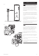
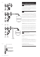
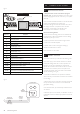
Pump
pre-wired
(mounted on
hydraulic station)
230V/240V~
Mains supply
L
N
E
Cylinder
sensor
Solar
differential
controller
Hydraulic Station
Solar panel
sensor
Terminal block
for extending
collector sensor
Double pole
isolating switch
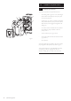
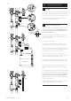
9.0 Installation of solar controller
9.1 Appliance installation
1. Always disconnect from the mains before opening the
controller cover. The solar differential temperature controller
is designed to be mounted on the front of the hydraulic
station. Alternatively it can be removed from the insulation and
be wall mounted (see panel below). In the case of wall
mounting the pump cable may need to be lengthened.
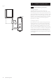
Alternative mounting option
In the case of wall installation proceed in the
following way:
Drill installation holes according to the dimensions
shown below. Screw in two upper screws up to 6 mm
distance. Open the appliance as described in section 10.2
and hang it onto two screws. Now two lower screws can be
mounted. Tighten all screws. Do not overtighten to avoid
damage to the controller backplate.
9.2 Opening the controller
1. Always disconnect from the mains before opening the
controller cover.
2. No tools are required to open the controller. The front of
the controller is secured by two latches which engage with the
controller backplate.
3. It can be opened by gently pulling the lower side edges
outwards and then hinging the front upwards.
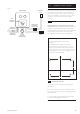
126mm
118mm
84mm
Fig. 22
The collector panel temperature sensor should be installed in
the sensor pocket at the collector array flow connector as
part of the first fix process. Ensure that the cable from this
sensor can be identified for connection to the pump station
wiring centre. Use the 13m extension cable supplied if
required.