
Specifications

23
3A Fused Supply
L
1
1
85 3
123E
2345678910Terminal Box (Not supplied)
23 1423 12387
NE LPLNE
SL L N E
DHW ON DHW OFF
Boiler Terminal Strip Programmer
5
Cylinder Auxiliary Controls
7
692
12N
Room Stat
1L
Solar
Controller
3
12E
Solar O/Temp Cutout
32
PE L N
Solar Differential Controller
11
A1
12
N
T1 T2 T4 T7
423
LNE
CH Pump
A1 N PE
11 12 E
Solar Pump
3 2 10 NOT USED
G/Y BL BR GR
2 Port Valve
OR
329 7
G/Y BL WH GR
3 Port Mid Position Valve
5
OR
6
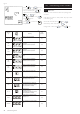
CH ON
See Fig. 23
3A Fused Supply
L
1
1
85 3
123E
2345678910Terminal Box (Not supplied)
23 1423 1219
NE LPLNE
SL L N 1 2
Boiler Terminal Strip Programmable Room Stat
5
Cylinder Auxiliary Controls
7
163
12E
Solar O/Temp Cutout
362
PE L N
Solar Differential Controller
11
A1
12 8 2
NA3N
T1 T2 T4 T5 T7
423
LNE
CH Pump
A1 N PE
11 12 E
Solar Pump
3 2 5 NOT USED
G/Y BL BR GR
DHW 2 Port Valve
OR
329 7
G/Y BL WH GR
3 Port Mid Position Valve
5
OR
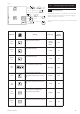
See Fig. 23
A2
N
A1 N PE
11 12 E
Solar Pump 2
A2 N
A1 N PE
11 12 E
Solar Pump 2
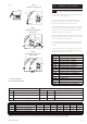
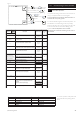
D. Auxiliary heating by boiler with 3 port mid position valve system
- no reheat control by solar controller.
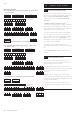
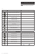
E. Auxiliary heating by boiler with 3 port mid position valve system
- reheat control by solar controller.
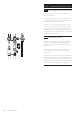
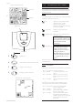
9.0 Installation of solar controller
9.8
1. Key to abbreviations:
L-Live
N - Neutral
E-Earth
PL - Pump Live
SL - Switched Live
G/Y - Green and Yellow
BL - Blue
BR - Brown
GR - Grey
OR - Orange
WH - White
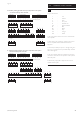
2. The wiring schemes assume the use of an unvented Solar
DHW cylinders.
3. These diagrams are presented for guidance only, terminal
numbers may differ between different manufacturers
equipment.
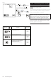
4. Main accept no liability for any loss or damage arising from
any errors or omissions that may be inadvertently contained
within these diagrams.
5. The various ancillary equipment manufacturers should be
consulted to confirm the correct operation of their products
within the system.
6. The Warranty only applies to equipment and controls
supplied with the system.
© Baxi Heating UK 2010
Fig. 26