
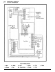
Technical data


13.0 Changing Components – page 30
13.1 Changing Components
IMPORTANT: When changing components ensure that
both the gas and electrical supplies to the boiler are
isolated before any work is started.
Hazardous materials are not used in the construction of
Baxi products, however reasonable care during service is
recommended.
1. Remove the outer case and lower door panel as
described under “Installation” Section 8.3.
2. Isolate the water circuits and drain as necessary.
There are 3 drain points:
a) Central heating flow valve.
b) Domestic hot water outlet elbow.
c) Central heating return valve.
NOTE: Do not use the Pressure Relief Valve to drain the
circuit.
3. Place a tube on drain point to drain water away from
electrics. Turn anticlockwise to open.
NOTE: When reassembling always fit new ‘O’ rings,
ensuring their correct location on the spigot. Green and
Violet “O” rings are used for gas joints and Black “O”
rings for water joints. Use Greasil 4000 (WRC Approved
Silicone Grease).
4. After changing a component re-commission the boiler
where appropriate.
To change the pressure switch - automatic air vent -
remove the airbox door panel by releasing the six ¼ turn
screws (Fig. 47).
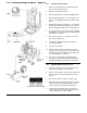
13.2 Pressure Switch (Fig. 46)
1. Noting the position of the electrical connections and
pressure pipes, remove them.
2. Remove the two screws holding the pressure switch to
the pressure switch mounting bracket.
3. Fit the new pressure switch and reassemble all
components in reverse order of dismantling.
13.3 Automatic Air Vent (Fig. 48)
1. Undo the air vent union nut and retain the sealing
washer.
2. Withdraw the air vent through the seal in the airbox.
3. Fit the new air vent and reassemble in reverse order.