Please leave these Instructions with the User Baxi Genesis Gas Fired Wall Mounted Combination Boiler Natural Gas, Propane & Butane Comp No. 236463 - 10/96 Baxi Genesis 80 – G.C.No 47 077 01 Baxi Genesis 96 – G.C.
Genesis Baxi Heating Ltd. Baxi Heating Ltd is one of the leading manufacturers of domestic heating products in the U.K. Our first priority is to give a high quality service to our customers. Quality is built into every Baxi product -products which fulfil the demands and needs of consumers, offering choice, efficiency and reliability.
Genesis Baxi Heating Ltd.
Genesis Baxi Heating Ltd. Introduction – Page 4 Description The Baxi Genesis is a fully automatic gas fired wall mounted combination boiler. It is room sealed and fan assisted, and will serve central heating and mains fed domestic hot water. Genesis 80 The boiler is preset to give a maximum output of 23.25 kW (79,347 Btu/hr) for both hot water and central heating modes. Genesis 96 The boiler is preset to give a maximum output of 28.0 kW (95,555 Btu/hr) for both hot water and central heating modes.
Genesis Baxi Heating Ltd.
Genesis Baxi Heating Ltd. Appliance Operation – Page 6 CENTRAL HEATING MODE With a demand for heating the pump (11) circulates water through the primary circuit. At a flow rate of approximately 250 I/hr the central heating flow switch (9) operates, commencing the ignition sequence. The main burner (6) ignites at 1/3 rate then switches to full gas rate. The gas valve (7) controls the gas rate “HIGH LOW” to maintain the heating temperature measured by the thermostat sensor (16).
Genesis Baxi Heating Ltd.
Genesis Baxi Heating Ltd.
Genesis Baxi Heating Ltd.
Genesis Baxi Heating Ltd. System Details – Page 10 The Genesis Combination Boiler is a ‘Water Byelaws Scheme - Approved Product’. To comply with the Water Byelaws your attention is drawn to the following installation requirements and notes (IRN). 1) 2) 3) IRN 001 - See text of entry for installation requirements and notes. IRN 116- Byelaw 90 and 91. IAN 302 - Byelaw 14.
Genesis Baxi Heating Ltd. SYSTEM DETAILS – Page 11 A filling point connection on the central heating return pipework must be provided to facilitate initial filling and pressurising and also any subsequent water loss replacement/refilling. The filling method adopted must be in accordance with all relevant water supply byelaws using approved equipment. Your attention is drawn to: IRN 302 and Byelaw 14.
Genesis Baxi Heating Ltd. SYSTEM DETAILS – Page 12 Domestic Hot Water Circuit All DHW circuits, connections, fittings etc should be fully in accordance with relevant standards and water supply bye-laws. Your attention is drawn to: IRN 116 and Byelaw 90 and 91. Sealed primary circuits and / or secondary hot water systems shall incorporate a means for accommodating the thermal expansion of water to prevent any discharge from the circuit and / or system except in an emergency situation.
Genesis Baxi Heating Ltd. Site Requirements – Page 13 The installation must be carried out by a CORGI Registered Installer or other competent person and be in accordance with the relevant requirements of GAS SAFETY (Installation and Use) REGULATIONS, the BUILDING REGULATIONS (Scotland) (Consolidation), the LOCAL BUILDING REGULATIONS, the current I.E.E. WIRING REGULATIONS and the bye laws of the LOCAL WATER UNDERTAKING.
Genesis Baxi Heating Ltd. SITE REQUIREMENTS – Page 14 Ventilation of Compartments Where the appliance is installed in a cupboard or compartment, air vents are required (for cooling purposes) in the cupboard or compartment at high and low level which may communicate with a room or direct to outside air. Detailed recommendations for air supply are given in BS 5440: Part 2. An existing cupboard or compartment may be used, provided that it is modified for the purpose.
Genesis Baxi Heating Ltd. SITE REQUIREMENTS – Page 15 Flue An internal fitting kit is available for installations where the flue terminal is inaccessible from the outside. -(Part No 236441). This is available from merchants or direct from Baxi free of charge. The following guidelines indicate the general requirements for siting balanced flue terminals. Recommendations for flues are given in BS 5440 Pt.1.
Genesis Baxi Heating Ltd. SITE REQUIREMENTS – Page 16 Flue Dimensions The standard flue supplied with the appliance is suitable for use with flue lengths between 220mm (8 21/32in) and 610mm (24in). TOTAL FLUE LENGTH PERMISSIBLE IS: 3 METRES MAX. Terminal Guard When codes of practice dictate the use of terminal guards, they can be obtained from most Plumbers and Builders Merchants nationwide. When ordering a terminal guard, quote the appliance model number.
Genesis Baxi Heating Ltd. Installation – Page 17 Initial Preparation Remove the fixing template from the small carton. After considering the site requirements (see page 13) position the template on the wall. Mark the position of the fixing holes for the two hooks. Use the upper two holes where possible. Mark the centre of the flue hole (rear exit). For side exit, mark as shown. If required, mark the position of the gas and water pipes. Remove the template.
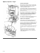
Genesis Baxi Heating Ltd. INSTALLATION – Page 18 Preparing The Boiler Follow the sequence depicted on the carton to unpack the boiler. Remove the lower cover poly bag assembly and contents kit before laying the boiler on its back supported by the polystyrene block. Hinge down the lower door panel and spring off. Remove the four securing screws, slide and lift away the outer case. Remove the sealing plugs from the copper bends. Stand the boiler on its base on the carton sleeve.
Genesis Baxi Heating Ltd. INSTALLATION – Page 19 Fitting The Boiler Lift the boiler using the lower edge of the combustion box and the hand holds in the chassis. Place boiler on the support bracket, slide back then lift to engage on top hooks. Hinge down the electrical box to gain access to the connections between boiler and valves. At both sides push in the two tabs - hinge box down by rotating. Check the inlet water filter is fitted (F). Make the gas connection first (G).
Genesis Baxi Heating Ltd. Fitting The Flue – Page 20 HORIZONTAL FLUE The standard flue supplied with the appliance is suitable for lengths 220mm minimum to 610mm maximum. Rear flue: maximum wall thickness - 490mm. Side flue, (left or right): maximum wall thickness - 477mm. If fitting the optional Intel fitting kit, flue extension kit or elbows refer to the instructions provided with the kits. Place the flue elbow on to the flue connection, with the outlets facing the wall opening.
Genesis Baxi Heating Ltd. Fitting The Flue – Page 21 Slide the rubber seal and clip over the air duct. Engage the flared end of the flue duct onto the flue elbow. Insert the flue duct into the air duct and engage it in the terminal. Slide the rubber sleeve over the joint between the air duct and elbow. Align the clip over the rubber seal. For neatness the screws on the clip flange should be below the air duct if possible, providing they remain accessible. Secure the clip.
Genesis Baxi Heating Ltd. Making The Electrical Connections – page 22 The electrical connections are on the right hand side of the unit. Undo the screws securing the small cover and remove the cover. Undo the screw securing the right hand cable clamp and hinge up. If fitting an integral timer kit please refer to kit instructions at this stage, paying particular attention to voltage requirements. Route the incoming electrical cable/s over the top edge of the support bracket.
Genesis Baxi Heating Ltd. Making The Electrical Connections – page 23 Fitting a Room Thermostat A 2-wire or 3-wire low voltage thermostat can be fitted to the Genesis plug. To fit a 2-wire thermostat, remove link, and wire the thermostat switch between positions 1 & 2. To fit a 3-wire thermostat, remove link, and wire the thermostat switch between positions 1 & 2. The anticipator should be wired to position 3, as this provides a continuous 24V supply.
Genesis Schematic Wiring Diagram – Page 24 44 - 45 Baxi Heating Ltd.
Genesis Baxi Heating Ltd.
Genesis Baxi Heating Ltd. Commissioning The Appliance – Page 26 Reference should be made to BS 5449 Section 5 when commissioning the appliance. Open the cold feed to the appliance. Open all hot water taps to purge the DHW system. Ensure that the filling loop is connected, and open the heating flow and return valves on the appliance. Open the automatic air vent. To help purge the primary circuit turn the pump on & off several times by using the ONOFF selector switch. Pressurise the system to 1.
Genesis Baxi Heating Ltd. Servicing The Appliance – Page 27 Annual Servicing For reasons of safety and economy, it is recommended that the appliance is serviced annually. To measure the Co% and (Co2% content of the flue products, remove the LH sample screw and insert a suitable sampling probe. Ensure that the appliance is cool. Ensure that both the gas and electrical supplies to the appliance are isolated. Remove the outer case and lower door panel (See Installation, p18).
Genesis Baxi Heating Ltd. Changing Components – Page 28 Ensure that both the gas and electrical supplies to the appliance are isolated. Remove the outer case and door panel as described under “Servicing the Appliance”. Isolate the water circuits and drain as necessary. There are five drain points: 1. 2. 3. 4. 5. Central heating flow valve. Domestic hot water outlet elbow. Domestic cold water inlet valve. Under three way valve. Under automatic air vent.
Genesis Baxi Heating Ltd. CHANGING COMPONENTS – Page 29 Gas Valve Solenoids All three solenoids are permanently fixed to the valve cover plate. Remove the electrical connections, having noted their positions. The wires are colour coded to each solenoid. Remove the screws holding the plate to the valve body. Remove the plate and gasket carefully to avoid losing the three valves and springs. Always fit a new gasket. Reassemble in reverse order of dismantling.
Genesis Baxi Heating Ltd. CHANGING COMPONENTS – Page 30 Heat Exchanger Remove the combustion box door as described under “Servicing the Appliance”. Undo the nut on the return pipe at the pump. Remove the “R” clip on the flow pipe at the manifold. Remove the clips securing the flow and return pipes to the heat exchanger. Ease the flow and .return pipes from the heat exchanger by gently pulling downwards. Pull the heat exchanger forwards and remove.
Genesis Baxi Heating Ltd. CHANGING COMPONENTS – Page 31 Pump (Head Only) Hinge down the electrical box. Remove the screw retaining the pump electrical cover and remove the cover. Disconnect the wires (L,N,E) and slide out the grommet assembly. Remove the four socket head screws securing the pump head, and seperate from the housing. Switch the new pump head to setting No3. Remove electrical cover and discard. Assemble new head with electrical box at 10 ‘o’Clock to housing.
Genesis Baxi Heating Ltd. CHANGING COMPONENTS – Page 32 PCB and Spark Generator Hinge down the electrical box. Remove the screws and small cover. Remove the three screws to release the cable clamp. Unplug the multipin connections to the two P.C.B.s as follows:1. 2. 3. 4. Mains input plug- (C). Pressure switch & fan - (D). Safety thermostat & sensing electrode - (E). Pump - (F). Unplug the-two spark electrode leads from the generator (G).
Genesis Baxi Heating Ltd. CHANGING COMPONENTS – Page 33 Spark Generator Disconnect generator lead at connection on power board (K). Lift power board partially from locating pegs to allow the release of the generator from its locating pins. Disconnect terminals to L, N & Earth. Replace spark generator or wiring as necessary. Reassemble in reverse order. POWER BOARD Disconnect spark generator lead at connection (K) on power board. Unplug the link plug connecting the two P.C.B.s at (B).
Genesis Baxi Heating Ltd. CHANGING COMPONENTS – Page 34 Thermistors The procedure is the same for both domestic hot water and central heating thermistors. Remove the electrical connection from the thermistor. Remove the spring clip retaining it to the manifold. Withdraw the thermistor. Reassemble in reverse order. Safety Thermostat Remove the electrical connections from the sensor. Remove the retaining clip from the flow pipe. Remove the sensor from the clip.
Genesis Baxi Heating Ltd. CHANGING COMPONENTS – Page 35 Expansion Vessel Hinge down the electrical box. Turn off gas tap and close all water valves. Drain as necessary. Undo all unions between the boiler and isolating valves, retaining the sealing washers. Remove the electrical cover, and unplug the input lead. Remove the earth connection from the grounding strip. Release the input cables from the cable clamp. Remove the screws holding the flue elbow to the boiler.
Genesis Baxi Heating Ltd. CHANGING COMPONENTS – Page 36 Remove the boiler from the wall by lifting to unhook then remove from the lower support bracket. Stand the boiler on its base and undo the two screws holding the vessel retaining bracket to the chassis. Remove the clip retaining the braided expansion tube to the manifold. Lift the vessel away from the boiler. Undo the screw holding the retaining bracket to the expansion vessel.
Genesis Baxi Heating Ltd. CHANGING COMPONENTS – Page 37 Pressure Relief Valve Close all water valves and drain as necessary. Disconnect the union between the valve and the discharge pipe. Slacken the grub screw retaining the valve. Pull the valve sideways to disengage it. Reassemble in reverse order. Pressure Gauge Hinge down the electrical box. Remove the spring fork clip retaining the gauge to the facia, and withdraw the gauge. Remove the clip retaining the capillary to the manifold.
Genesis Baxi Heating Ltd. CHANGING COMPONENTS – Page 38 Flame Sensing Probe Remove combustion box door, and hinge down electrical box. Disconnect the sensor lead from the main wiring loom (in line amp tag). Pull the lead through the grommet in the combustion box lower panel. Slacken the screws holding the burner flange, and remove the flange. Remove the screw securing the probe to the burner. Remove assembly from the burner by rotating forwards. Lift out and thread lead between burner blades.
Genesis Baxi Heating Ltd. CHANGING COMPONENTS – Page 39 lnjector Manifold Remove the combustion box door. Remove the six screws holding the manifold to the burner and inlet pipe. Remove the burner flange and draw the manifold forwards. Reassemble in reverse order. 3 - Way Valve Close central heating isolating valves and drain down. Release union nut and remove ‘R’ clip on central heating outlet pipe. Pull forward to disengage pipe spigot. Remove ‘R’ clip securing the by pass pipe to the valve.
Genesis Baxi Heating Ltd. CHANGING COMPONENTS – Page 40 Domestic Hot Water Filter Undo the nut on the DHW inlet bend. Swivel the bend to gain access to the flat filter. AUTOMATIC AIR VENT Unscrew the air separator head assembly. Replace unit in reverse order. Central Heating Filter Undo the nut on the central heating return bend. Remove the ’R’ clip on the connection at the manifold and remove the filter. Clean or replace filter/s as necessary. Reassemble in reverse order.
Genesis Baxi Heating Ltd. CHANGING COMPONENTS – Page 41 Flow Regulator To remove the flow regulator use a small screwdriver to lever the plastic housing out of the valve inlet. Fit the replacement regulator ensuring it is inserted in the direction shown.
Genesis Operational Flow Chart – Page 42 - 43 42 - 43 Baxi Heating Ltd.
Genesis Operational Flow Chart – Page 44 - 45 44 - 45 Baxi Heating Ltd.
Genesis Fault Finding – Page 46 46 Baxi Heating Ltd.
Genesis Baxi Heating Ltd.
Genesis FAULT FINDING – Page 48 48 Baxi Heating Ltd.
Genesis Baxi Heating Ltd.
Genesis Electronic Board Detail – Page 50 50 Baxi Heating Ltd.
Genesis Baxi Heating Ltd. Short Parts List – Page 51 Key Description G.C.