Please leave these instructions with the user Baxi Belmont 2 & Baxi Wentworth Classic Fan Flue Live Fuel Effect Inset Gas Fires Comp No 244628 - Iss 5 - 2/00 Installation and Servicing Instructions
Page 2 Natural Gas BaxI Belmont 2 Fan Flue G.C. No 32 075 23 BaxI Wentworth Classic Fan Flue G.C. No 32075 14A Baxi Limited is one of the leading manufacturers of domestic heating products in the UK. Our first priority is to give a high quality service to our customers. Quality is built into every Baxi product - products which fulfil the demands and needs of customers, offering choice, efficiency and reliability.
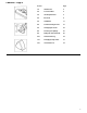
Contents - Page 3 Section Page 1.0 Introduction 4 2.0 Technical Data 6 3.0 Site Requirements 7 4.0 Electrical 9 5.0 Installation 11 6.0 Commissioning the Fire 21 7.0 Arranging the Coals 22 8.0 Checking for Spillage 25 9.0 Fitting the Trim & Fender 26 10.0 Annual Servicing 27 11.0 Changing Components 31 12.
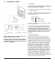
1.0 Introduction - Page 4 1.1 Description 1. The Baxi Belmont 2 and Wentworth Classic Fan Flue are live fuel effect inset gas fires designed to be used on Natural Gas only at a setting pressure of 20 mbar. 2. The appliance is designed to give a maximum heat output of 3.0 kW (10,236 Btu/h). 3. The fire is controlled by a knob which is positioned behind the controls access door on the fender assembly (Fig. 1).
1.0 Introduction - Page 5 1.3 Installation 1. The appliance is suitable for installation only in G.B. and I.E. and should be installed in accordance with the rules in force. For Ireland install in accordance with l.S.813 ‘installation of Gas Appliances”.
2.0 Technical Data - Page 6 Belmont 2 Fan Flue Wentworth Classic Fan Flue Category of Appliance 2H The fire is set for Gas Type G20 at 20mbar. Heat Input (net) kW Btu/h High 6.16 21,018 Heat Output kW Btu/h High 3.0 10,236 Inlet Setting Pressure mbar in wg Terminal Position with Minimum Distance (Fiq. 17) A B C D E F G H I J K L 6 Directly below an openable window or other opening, e.g. an air brick. Below gutters, soil pipes or drain pipes. Below eaves. Below balconies or car port roof.
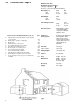
3.0 Site Requirements - Page 7 3.1 Location 1. The Baxi Belmont 2 and Wentworth Classic Fan Flue gas fires must be installed on an outside wall. The maximum distance from the rear face of the fire mounting frame to the outside face of the wall is 600mm. The minimum is 300mm. The effective wall thickness can be increased by the addition of an internal fire surround. 2. The flue terminal must be located in a suitable position on an outside wall taking into consideration the dimensions shown in Fig. 3. 3.
3.0 Site Requirements - Page 8 3.5 Clearances (Fig. 7) 1. Shelf Clearance - minimum clearance from the hearth to the underside of a combustible shelf should be 830mm (3221/32 in) provided the shelf depth is 150mm (529/32 in) or less. When the shelf depth is increased by increments of 12.5mm (15/32 in) greater than 150mm (529/32 in), add 25mm (1in) to the 830mm (3221/32 in). 2.
4.0 Electrical - Page 9 4.1 Electrical Supply & Connection 1. All extemal wiring to the appliance must be in accordance with the latest I.E.E. Wiring Regulations and any local regulations that apply. 2. Ensure that any cables are not pulled tight and that it is possible to isolate the electrical supply to the fire for servicing. 3. In the event of an electrical fault after installation of the appliance, preliminary electrical system checks must be carried out i.e.
4.0 Electrical - Page 10 4.
5.0 Installation - Page 11 5.1 Initial Preparation 1. Unpack the appliance from the carton and check all items are present. The ceramic coal bed items should be left in their box until required. 2. Some sheet metal parts may be fitted with protective plastic coating which must be removed prior to installation. 5.2 General Preparation 1. Make sure the chosen position will comply with the installation requirements detailed in section 3.0 Site Requirements. 2.
5.0 Installation - Page 12 5.3 Preparation of the Site (cont) 4. Measure 400mm up from hearth level and mark this dimension on the wall. Drill through the inner and outer walls at the mark using a suitable pilot drill at a point corresponding to the centre line of the fire flue outlet (Fig. 14). 5. From outside consider the position of the pilot hole in relation to the brickwork. The fan box is 3 bricks high and requires a cut-out in the wall 95mm above and 120mm below the pilot hole.
5.0 Installation - Page 13 5.4 Preparation of the Site - Fire fitted Into a recess 1. A suitable liner should be made to enclose the fire (Fig. 16). This should be fitted within the false fire surround. It should be 24mm thick and be of Supalux or similar noncombustible board. If 24mm material is not available two or more smaller boards may be used. It should extend from the front of the fire mounting face to the inside face of the outside wall.
5.0 Installation - Page 14 5.4 Preparation of the Site - Timber Frame Dwelling 9. This installation requires a 150mm diameter piece of single wall flue pipe or similar for use as a metal sleeve (Fig. 19). 10. This installation details the use of a fire surround or false chimney breast, having a minimum depth of 140mm, which allows the fire to be positioned in front of the wall with a hole in the inner wall for the flue only. The maximum surround depth will depend upon the wall thickness.
5.0 Installation - Page 15 5.4 Preparation of the Site (cont) 16. Taking into consideration the dimensions in fig.13 and 14 on page 12 and the position of the pilot hole, cut a suitable hole for the flue box assmebly. 17. Once the height of the flue has been determined make a hole through the wall to accept a 150mm diameter sleeve. Ensure that when the 150mm diameter hole is cut through the wall and the rectangular recess is cut in the outer wall, no timbers are cut. 18.
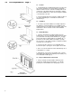
5.0 Installation - Page 16 5.5 Fitting the Fan Box 1. Place the power supply cable and fan to fire harness in their intended positions, passing through the hole in the wall where applicable. 2. Either fit the liner into the recess and pass the fan to fire harness through the hole in the liner, or complete the false chimney breast or surround incorporating the liner as appropriate. 3. Unpack the fan box assembly and undo the screws retaining the brown fan box cover.
5.0 Installation - Page 17 5.5 Fitting the Fan Box (cont) 14. Locate the fan box and flue assembly in the flue box collar and secure with the screws previously removed and refit the pressure switch bracket (Fig. 23). Reconnect the sensing tube (Fig. 24). 15. Fit the fan box cover to the fan box assembly. A TERMINAL GUARD IS RECOMMENDED Baxi Heating Part No 245770. Position the guard over the fan box. Ensure the guard is equally spaced about the fan box.
5.0 Installation - Page 18 5.6 Fitting the Fire 1. There are 2 methods of fixing the fire in position, using the eyebolts and cables or simply screwing through the outer fire frame with 4 screws to the wall or surround face. NOTE: It is recommended that the appliance is screwed to the wall or surround face. The eyebolt and cable method can only be used when the appliance is installed in a false chimney breast or surround. 2. Either mark the wall as shown (Fig.
5.0 Installation - Page 19 5.6 Fitting the Fire (cont) SCREW FIXING METHOD 1. Fit the fan box harness lead through the hole at the right hand side of the fire. Do not draw any more of the harness into the fire than is necessary. 2. Position the appliance in front of the fireplace opening. Manoeuvre the appliance backwards into the opening (Fig. 28). 3. Secure the fire in position using suitable screws in the previously drilled and plugged holes. 4.
5.0 Installation - Page 20 5.6 Fitting the Fire (cont) CABLE TENSION METHOD OF FIXING 1. Engage the tensioning nuts on the threaded shanks of the tensioning devices. Run the nuts down to the hexagonal heads of the tensioning devices (Fig. 29). 2. From the front insert the cable tensioning devices through the combustion box rear panel. The hexagonal heads must be to the inside of the box (Fig. 29). 3. Fit the fan box harness through the hole at the right hand side of the fire.
6.0 Commissioning the Fire - Page 21 6.1 Checking Gas Soundness 1. Turn on the gas supply and check for gas soundness with leak detection fluid (BS 6891). 6.2 Checking OperatIon of the Fire 1. Turn off the gas supply. Remove the screw from the pressure test point on the gas inlet elbow and connect a suitable pressure gauge (Fig. 32). 2. Check that the electrode is sparking to the burner (Fig. 33) when the control knob is pushed in and rotated anticlockwise past the ignition position ( ) (Fig. 35). 3.
7.0 Arranging the Coals - Page 23 7.1 Identification It is Important that all the firebed components are used and arranged as shown In order to achieve the desired flame picture. Ensure all firebed components are present and Identified prior to Installation. 1. Remove the coals, and front and rear coal mouldings from their packaging and place them on a newspaper or similar to prevent soiling furnishings. CAUTION: The coals are extremely fragile and must be handled accordingly.
7.0 Arranging the Coals - Page 23 7.2 Arranging the Coalbed NOTE: It is important for the safe operation of the appliance that the front and rear coal mouldings are correctly located and in accordance with these instructions. 1. Carefully position the rear coal moulding into the rear of the fire. The undercut in the base of the moulding should rest on the tabs of the rear coal support. The back face of the moulding should sit on the rear coal support.
7.0 Arranging the Coals - Page 24 7.3 Arranging the Loose Coals NOTE: Do not allow any of the coals to fall into the gap between the front and rear coal mouldings. 1. Take 2 coals and place on the outer edges of the front coal moulding (Fig. 40). 2. Take 4 coals and place as shown in Fig. 41 bridging the front and the rear coal mouldings. Ensure that the flat faces on these coals face downward. 3. Take the 5 remaining coals and place as shown in Fig.
8.0 Checking for Spillage - Page 25 8.1 Checking for Spillage CAUTION-Whilst checking for spillage care must be taken to avoid touching hot panels. 1. Before starting the test close all doors and windows. 2. Operate the fire from cold at maximum input. 3. After approximately five minutes check for spillage. 4.
9.0 Fitting the Trim & Fender - Page 26 9.1 Fitting the Trim and Fender (Fig. 45) 1. Carefully remove the trim and fender from their packaging. 2. Align the trim with the fire outer frame. The trim has four keyhole type cutouts on the inside edge which locate on the tabs on the black side trims. 3. Place the fender assembly centrally between the legs of the trim and push it back as far as possible. 4.
10.0 Annual Servicing - Page 27 10.1 Maintenance IMPORTANT: It is possible that some soot may be deposited on the coals after use. This is acceptable providing it is not allowed to accumulate. CAUTION: The coals are extremely fragile and must be handled accordingly. To avoid soiling ones hands, gloves should be worn and any inhalation of the dust should be avoided. Keep the coals away from children at all times. Never use coals other than those supplied or Genuine Baxi Spare Parts.
10.0 Annual Servicing - Page 28 10.2 Preparation 1. For reasons of safety and economy it is important to service the fire annually. WARNING: Isolate the gas and electrical supplies to the appliance before servicing. 2. Remove the controls access door and fender assembly (Fig. 46). 3. Remove the trim (Fig. 46). 4. Carefully remove all the loose coals, and the front and rear coal mouldings (Fig. 47). 5. Undo the gas supply at the disconnecting union.
10.0 Annual Servicing - Page 29 10.3 Cleaning the Burner and Injectors 1. Undo the screw retaining the spark electrode to the burner tray (Fig. 50). 2. Undo the screw retaining the burner to the burner tray (Fig. 51). 3. Slide the burner to the left to disengage from the injector. Rotate the electrode slightly and lift the burner out of the tray. 4. Using a soft brush remove any dirt from the burner and ensure all ports are free from obstruction. 5.
10.0 Annual Servicing - Page 30 10.5 Cleaning the Electrode (Figs. 54 & 55) 1. Check for any signs of cracking or other damage to the ceramic. 2. Clean the electrode wire if necessary. 3. Upon re-assembly check the spark gap is 2.5-4.0mm. 10.6 Cleaning the Fan 1. From outside remove the terminal guard and fan box cover (Fig. 57). 2. Undo the screws holding the fan outlet plenum to the fan box. Manouvre the plenum from the box taking care not to damage the rear gasket (Fig. 56).
11.0 Changing Components - Page 31 11.1 Changing Components WARNING: Isolate the gas and electrical supplies to the appliance before changing any components. 1. Remove the controls access door and fender assembly (Fig 59). 2. Carefully remove all the loose coals and the front and rear coal mouldings. CAUTION: The coals are extremely fragile and must be handled accordingly. To avoid soiling ones hands, gloves should be worn and any inhalation of the dust should be avoided.
11.0 Changing Components - Page 31 11.2 Removal of Controls / Burner Chassis Assembly 1. If any of the controls components are to be renewed the burner chassis assembly must be removed from the appliance. 2. Undo the gas supply at the disconnecting union. If necessary remove any pipework between the union and inlet elbow (Fig. 60). 3. Undo the three screws retaining the burner chassis assembly to the combustion box sides and combustion box base. Withdraw the burner chassis assembly (Fig. 61). 11.
11.0 Changing Components - Page 33 11.5 Electrode (Fig. 65) 1. Disconnect the electrode lead from the tag at the base of the electrode. 2. Undo the screw retaining the electrode to the burner tray and withdraw. 3. Fit the new electrode and re-assemble in reverse order. Check that the spark gap is between 2.5mm and 4.0mm. 11.6 Thermocouple 1. Remove the burner as described in section 11.3. 2. Undo and remove the locknut holding the thermocouple to the burner tray (Fig. 66). 3.
11.0 Changing Components - Page 34 11.7 Gas Tap and Piezo Unit (Fig. 69) 1. Remove the burner as described in section 11.3. 2. Undo the thermocouple nut from the rear of the gas valve. 3. Undo the union nuts connecting the gas inlet pipe and the gas feed pipe to the injector from the body of the gas valve. 4. Disconnect the electrode lead from the piezo unit. 5. Pull away the control knob (Fig. 68) from the gas valve shaft. 6.
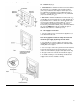
11.0 Changing Components - Page 35 11.9 Fan (Fig. 70 & 71) 1. From outside remove the terminal guard and fan box cover. 2. Undo the screw holding the fan outlet plenum to the fan box. Manouvro the plenum from the box taking care not to damage the rear gasket (Fig. 70a). Note the position of the three wires to the fan and remove them. Disconnect the sensing tube from the fan. 3. Rotate the complete fan approximately 20º anti-clockwise to disengage it from the fan box. Lift the fan clear of the box. 4.
11.0 Changing Components - Page 36 11.12 Fan Control Unit 1. From outside remove the terminal guard and fan box cover (Fig. 74). 2. Undo the four screws holding the fan box to the fan box collar and draw the fan box out. Disconnect the 8-way plug and undo the earth screw from the rear of the fan box. Completely remove the fan box from the wall. 3. Undo the screws securing the pressure switch bracket to the fan box and draw the bracket forwards (Fig. 75). 4. Pull the sensing tube off the fan.
12.0 Short parts list - Page 37 12.1 Short Parts List Click here for Helplines 38 Manufacturers Part No. Key No. G.C. No.