Baxi Wentworth PCF Classic Baxi Kingston 2 PCF Classic Baxi Belmont 2 Live Fuel Effect Inset Gas Fires Comp No 243046 - Iss 4 – 6/00 Installation and Servicing Instructions Please leave these instructions with the user
Page 2 Natural Gas Baxi Wentworth PCF Classic G.C. No 32 075 13A Baxi Kingston 2 PCF Classic G.C. No 32 075 19A Baxi Belmont 2 G.C. No 32 075 22 Baxi Limited is one of the leading manufacturers of domestic heating products in the UK. Our first priority is to give a high quality service to our customers. Quality is built into every Baxi product -products which fulfil the demands and needs of customers, offering choice, efficiency and reliability.
Contents - Page 3 Section Page 1.0 Introduction 4 2.0 Technical Data 6 3.0 Site Requirements 7 4.0 Installation 11 5.0 Commissioning the Fire 13 6.0 Arranging the Coals 14 7.0 Checking for Spillage 17 8.0 Fitting the Trim & Fender 18 9.0 Annual Servicing 19 10.0 Changing Components 23 11.
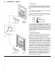
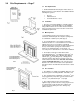
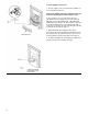
1.0 Introduction – Page 4 1.1 Description 1. The Baxi Wentworth PCF, Kingston 2 PCF Classic or Belmont 2 are live fuel effect inset gas fires designed to be used on Natural Gas only at a setting pressure of 20 mbar. 2. The appliances are designed to give a maximum heat output of 3.8 kW (13,000 Btu/h). 3. The fire is controlled by a knob which is positioned behind the controls access door on the fender assembly (Fig. 1).
1.0 Introduction – Page 5 1.3 Installation 1. The appliance is suitable for installation only in G.B. and I.E. and should be installed in accordance with the rules in force. For Ireland install in accordance with I.S.813 “Installation of Gas Appliances”.
2.0 Technical Data – Page 6 Kingston 2 PCF Classic Wentworth PCF Classic Category of Appliance 2H The fire is set for Gas Type G20 at 20mbar. Category of Appliance 2H The fire is set for Gas Type G20 at 20mbar. Heat Input (net) High Min Heat Input (net) High Min KW 6.16 2.4 KW 6.16 2.4 Btu/h 21,018 8,200 Btu/h 21,018 8,200 Heat Output High Heat Output High KW 3.8 KW 3.8 Btu/h 13,000 Btu/h 13,000 Cold Inlet Setting Pressure Cold Inlet Setting Pressure mbar 20 ± 1.
3.0 Site Requirements – Page 7 3.1 Site Requirements 1. The Baxi Wentworth PCF, Kingston 2 PCF Classic or Belmont 2 gas fires can be fitted to an installation with the following flue systems: • • • Pre-cast Fabricated steel Conventional brick or stone 3.2 Ventilation 1. No purpose provided ventilation is normally required for the appliance, normal adventitious room ventilation being sufficient. Reference should be made to BS 5871 Part 2.
3.0 Site Requirements – Page 8 3.5 Twin Walled Metal Flue Boxes 1. A double walled metal flue system conforming to the constructional requirements of BS 715 with a minimum internal flue diameter of 125mm (5in) should be used. The flue box should be of the Selkirk LFE 125 type or similar. 2. Remove the restrictor plate from the fire before fitting to this type of flue (Fig. 5). 3.
3.0 Site Requirements – Page 9 3.8 Clearances (Fig. 9) 1. Shelf Clearance - minimum clearance from the hearth to the underside of a combustible shelf should be 830mm (32 21/32 in) provided the shelf depth is 150mm (5 29/32 in) or less. When the shelf depth is increased by increments of 12.5mm ( 15/32 in) greater than 150mm (5 29/32 in) add 25mm ( 1 in) to the 830mm (32 21/32 in). 2.
3.0 Site Requirements – Page 10 3.10 Gas Supply & Connection 1. The gas supply is to be connected to the appliance as a concealed fix from the rear. Turn off any appliances that are fed by the meter and isolate the gas supply by turning off at the meter. 2. The supply is to be a concealed connection, it is advisable to route the supply to the left side of the unit taking into account the requirements of BS 6891:1988 dealing with enclosed pipes.
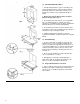
4.0 Installation – Page 11 4.1 Initial Preparation 1. Unpack the appliance from the carton and check all items are present. The ceramic coal bed items should be left in their box until required. 2. Some sheet metal parts may be fitted with protective plastic coating which must be removed prior to installation. 4.2 Fitting the Fire 1. If the fire is to be fitted in a flue box or a 5 inch lined flue, remove the restrictor plate from the rear of the appliance (Fig. 13).
4.0 Installation – Page 12 4.2 Fitting the Fire (cont) 8. Engage the tensioning nuts on the threaded shanks of the tensioning devices. Run the nuts down to the hexagonal heads of the tensioning devices (Fig. 16). 9. From the front insert the cable tensioning devices through the combustion box rear panel. The hexagonal heads must be to the inside of the box (Fig. 16). 10. Position the appliance in front of the fireplace opening and insert the cables in the holes In the combustion box rear flange (Fig.17).
5.0 Commissioning the Fire – Page 13 5.1 Checking Gas Soundness 1. Turn on the gas supply and check for gas soundness with leak detection fluid (to BS 6891). 5.2 Checking Operation of the Fire 1. Remove the screw from the pressure test point on the gas inlet elbow and connect a suitable pressure gauge (Fig. 20). 2. Check that the electrode is sparking to the burner (Fig. 21) when the control knob is pushed in and rotated anticlockwise passed the ignition position ( ) (Fig. 23). 3.
6.0 Arranging the Coals – Page 14 6.1 Identification It is important that all the firebed components are used and arranged as shown in order to achieve the desired flame picture. Ensure all firebed components are present and identified prior to installation. 1. Remove the coals, front and rear coal mouldings from their protective packaging and place them on a newspaper or similar to prevent soiling furnishings. CAUTION: The coals are extremely fragile and must be handled accordingly.
6.0 Arranging the Coals – Page 15 6.2 Arranging the Coalbed NOTE: It is important for the safe operation of the appliance that the front and rear coal mouldings are correctly located and in accordance with these instructions. 1. Carefully position the rear coal moulding into the rear of the fire. The undercut in the base of the moulding should rest on the pertrudng tabs of the rear coal support.
6.0 Arranging the Coals – Page 16 6.3 Arranging the Loose Coals NOTE: Due care and attention to these instructions should be taken when positioning the loose coals. Do not allow the coals to drop in the gap between the front and rear coal mouldings. 1. Take 2 coals and place on the outer edges of the front coal moulding (Fig. 28). 2. Take 4 coals and place as shown in Fig. 29 bridging the front coal moulding and the rear coal moulding, ensure and flat faces on these coals face downward.
7.0 Checking for Spillage – Page 17 7.1 Checking for Spillage CAUTION-Whilst checking for spillage care must be taken to avoid touching hot panels. 1. Before starting test close all doors and windows. 2. Operate the fire from cold at maximum Input. 3. After approximately five minutes check for spillage. 4.
8.0 Fitting the Trim & Fender – Page 18 8.1 Fitting the Trim and Fender 1. Carefully remove the trim and fender from their packaging. Place trim on its back to prevent falling over. 8.2 Wentworth, Belmont 2 Models (Fig. 33) 1. Align the trim with the fire outer frame. The trim has four keyholes type cutouts on the inside edge which locate on the keyways of the black side trims. 2. Place the fender assembly centrally between the legs of the trim and push it back as far as possible. 3.
9.0 Annual Servicing – Page 19 9.1 Maintenance IMPORTANT: It is possible that some soot may be deposited on the coals after use. This is acceptable providing it is not allowed to accumulate. CAUTION: The coals are extremely fragile and must be handled accordingly. To avoid soiling ones hands, gloves should be worn and any inhalation of the dust should be avoided. Keep the coals away from children at all times. Never use coals other than those supplied or Genuine Baxi Spare Parts.
9.0 Annual Servicing – Page 20 9.2 Preparation 1. For reasons of safety and economy it is important to service the fire annually. WARNING: Isolate the gas supply to the appliance before servicing. 2. Remove the controls access door and fender assembly (Fig. 35). 3. Remove the trim by lifting outwards and upwards over slots (Fig. 35). 4. Carefully remove all the loose coals, and the front and rear coal mouldings (Fig. 36). 5. Undo the disconnecting union on the gas supply (Fig. 37). 6.
9.0 Annual Servicing – Page 21 9.3 Cleaning the Burner and Injectors 1. Undo the screw retaining the spark electrode to the burner tray (Fig. 40). 2. Undo the screw retaining the burner to the burner tray (Fig. 41). 3. Slide the burner to the left to disengage from the injector. Rotate the electrode slightly and lift the burner out of the tray. 4. Using a soft brush remove any dirt from the burner and ensure all ports are free from obstruction. 5.
9.0 Annual Servicing – Page 22 9.5 Cleaning the Electrode (Fig. 44 & 45) 1. Check for any signs of cracking or other damage to the ceramic. 2. Clean the electrode wire if necessary. 3. Upon re-assembly check the spark gap is 2.5-4.0mm. 9.6 Completing Servicing 1. Clean any dirt and debris from the combustion box and fireplace recess. 2. Reassemble the fire in reverse order of dismantling and refit into the opening. 3. Recommission the fire.
10 0 Changing Components – Page 23 10.1 Changing Components WARNING: Isolate the gas supply to the appliance before changing any components. 1. Remove the controls access door and fender assembly (Fig 46 or 47). 2. Carefully remove all the loose coals and the front and rear coal mouldings. CAUTION: The coals are extremely fragile and must be handled accordingly. To avoid soiling ones hands, gloves should be worn and any inhalation of the dust should be avoided.
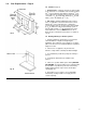
10.0 Changing Components – Page 24 10.4 Removal of Controls/Burner Chassis Assembly 1. If any of the controls components are to be renewed the burner chassis assembly must be removed from the appliance. 2. Undo the gas supply at the disconnecting union. If necessary remove any pipework between the union and inlet elbow (Fig. 48). 3. Undo the three screws retaining the burner chassis assembly to the combustion box sides and combustion box base. Withdraw the burner chassis assembly (Fig. 49). 10.5 Burner 1.
10 Changing Components – Page 25 10.7 Electrode (Fig. 53 & 54) 1. Disconnect the electrode lead from the tag at the base of the electrode. 2. Undo the screw retaining the electrode to the burner tray and withdraw. 3. Fit the new electrode and re-assemble In reverse order. Check that the spark gap is between 2.5mm and 4.0mm. 10.8 Thermocouple 1. Remove the burner as described in section 10.5. 2. Undo and remove the locknut holding the thermocouple to the burner tray (Fig. 55). 3.
10.0 Changing Components – Page 26 10.9 Gas Tap and Piezo Unit (Fig. 59) 1. Remove the burner as described in section 10.5. 2. Undo the thermocouple nut from the rear of the gas valve. 3. Undo the union nuts connecting the gas inlet pipe and the gas feed pipe to the injector from the body of the gas valve. 4. Disconnect the electrode lead from the piezo unit. 5. Pull away the control knob from the gas valve shaft. 6.
11.0 Short Parts List – Page 27 11.1 Short Parts List Key No. G.C. No. Description Manufacturers Part No.