
Technical data

5.0 Site Requirements
17
© Baxi Heating UK Ltd 2014
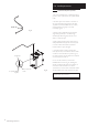
5.9 Condensate Drain - General
1. Ensure the discharge of condensate complies with any national
or local regulations in force. BS 6798 & Part H1 of the Building
Regulations give further guidance.
2. If any further drain pipe is required (additional to that supplied
with the boiler), it should be run in a proprietary material suitable
for condensate e.g. PVC, PVC-U, ABS, PVC-C or PP. John Guest
‘Speedfit’ components are recommended. Metal pipework is
NOT suitable for use in condensate discharge systems.
3. In all cases discharge pipe must be installed to aid disposal of
the condensate. To reduce the risk of condensate being trapped,
as few bends and fittings as possible should be used and any
burrs on cut pipe removed.
4. It is advisable that the full length of condensate pipe is run
internally and strongly recommended that this discharges
internally into the household drainage system. Where this is not
possible, discharge into an outside drain is permissible providing
every possible precaution is taken to prevent freezing.
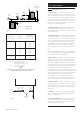
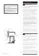
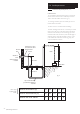
5. Any part of the condensate drain system that is outside the
dwelling, or in an unheated part of it must be kept to a
minimum and be at least 32mm diameter* & suitably insulated.
Any insulation outside the dwelling must be of a material
suitable for external use.
* Where the drain is still under the influence of the pump it is
unnecessary to increase the diameter e.g. underfloor as shown in
Fig. 17
6. When discharging condensate into a soil stack or waste pipe
the effects of existing plumbing must be considered. If soil pipes
or waste pipes are subjected to internal pressure fluctuations
when WC's are flushed or sinks emptied then back-pressure may
force water out of the boiler trap and cause appliance lockout.
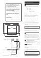
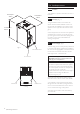
5.10 Condensate Pump & Sump
1. This boiler incorporates an automatic pumped condensate
system. The pump is submerged in a sump assembly (total
volume 1.5 litres) and is activated by the discharge float switch. A
second (safety) float switch is fitted.
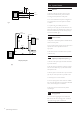
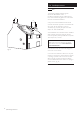
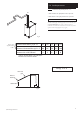
2. The pump has an effective head of 3 metres (Fig. 12). The
condensate case outlet connection is positioned at the top left of
the boiler (approximately 0.5 metres above the pump). It is
10mm diameter plastic.
3. The pump operates for 5 seconds when mains voltage is
applied to the boiler, e.g. when the power has been interrupted
and then reinstated. The pump will also run for 5 seconds if the
boiler reset rocker switch has been operated.
4. When the level of condensate in the sump is sufficient to
activate the discharge float switch the pump will run for 20
seconds, during which time approximately 1.7 litres of
condensate can be discharged.
5. In the event of condensate not being discharged the safety
float switch will operate for up to 130 seconds when the volume
of condensate in the sump reaches 1.05 litres. If the safety float
switch is activated for more than 130 seconds the boiler will
lockout.
Boiler
Max. Head
2.5 metres
(as measured
from the
case outlet)
Gravity Drain
min. fall 3°
Min. radius 100mm
10mm Outlet
Max. Head
3 metres
(as measured from
the pump outlet)
Fig. 12
IMPORTANT NOTES:
FAILURE TO INSTALL THE CONDENSATE DISCHARGE
PIPEWORK CORRECTLY WILL AFFECT THE RELIABLE
OPERATION OF THE BOILER.
CAREFUL CONSIDERATION MUST BE GIVEN TO THE
POSSIBILITY OF THE PIPEWORK BEING SUBJECT TO
FREEZING CONDITIONS AND APPROPRIATE MEASURES
TAKEN TO PREVENT BLOCKAGE.
CORRECT INSTALLATION IN ACCORDANCE WITH THIS
SECTION WILL CONSIDERABLY MINIMISE THE
LIKELIHOOD OF BLOCKAGE AND SUBSEQUENT
BOILER LOCK-OUT.