
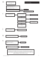
Technical data

34
© Baxi Heating UK Ltd 2014
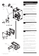
9.9 PCB (Fig. 61)
1. Pull off the two control knobs and disengage the securing
tabs of the cover. Undo the screws securing the PCB.
2. Draw the PCB forwards and disconnect the wiring.
Transfer the two potentiometer drive pins to the new PCB
and replace in reverse order of dismantling.
3. Ensure that the wiring connectors are pushed fully on to
the PCB terminals.
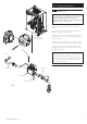
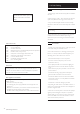
9.10 NTC (Fig. 60)
1. Disconnect the 2 pin plug. Remove the clip retaining the
NTC in the heat exchanger pocket. Pull the NTC out of the
pocket.
2. Apply suitable heat transfer paste to the new NTC.
Replace in reverse order of dismantling, using the clip
previously removed. Ensure that the plug is fully engaged.
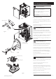
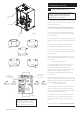
9.11 Safety Thermostat (Fig. 59)
1. Disconnect the two leads from the thermostat.
2. Remove the screws securing the thermostat to the
mounting plate on the flow pipe.
3. Replace in reverse order. The thermostat is not polarised
- either wire can fit either terminal on the thermostat.
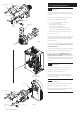
9.12 Float Switches (Fig. 62)
1. Remove the fan as described in Section 9.5, paragraphs 1
to 5.
2. The two float switches are the same, but oriented
differently. The discharge switch is at the left, the safety at
the right.
3. To remove either switch disconnect the lead and pull off
the alignment bracket.
4. Undo the retaining nut. The sealing grommet will be
released from the sump body and allow the switch to be
removed.
5. Note the orientation of the alignment rib on the switch. It
is positioned uppermost on the safety float switch and to
the bottom on the discharge switch.
6. Take the new switch assembly and insert it into the sump.
Hand tighten the nut and slide the alignment bracket in
place to ensure the switch is in position. Tighten the nut a
further 2 turns.
7. Reconnect the lead to the switch, ensuring it is fully
engaged
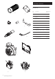
9.0 Changing Components
Discharge
Float Switch
Safety Float
Switch
PCB
Control Knobs
Safety Thermostat
Flow Pipe
Clip
NTC
Fig. 59
Fig. 60
Fig. 61
Fig. 62
Alignment
Bracket