Installation & Servicing Instructions Baxi Combi 130 HE Gas Fired Wall Mounted Condensing Combination Boiler Please leave these instructions with the user
Natural Gas Baxi Combi 130 HE G.C.No 47 075 04 Baxi is one of the leading manufacturers of domestic heating products in the UK. Our first priority is to give a high quality service to our customers. Quality is designed into every Baxi product - products which fulfil the demands and needs of customers, offering choice, efficiency and reliability.
Contents Section Page 0.0 Legislation 4 1.0 Introduction 5 2.0 General Layout 6 3.0 Appliance Operation 7 4.0 Technical Data 8 5.0 Dimensions and Fixings 9 6.0 System Details 10 7.0 Site Requirements 13 8.0 Installation 19 9.0 Electrical 26 10.0 Commissioning the Boiler 28 11.0 Fitting the Outer Case 32 12.0 Servicing the Boiler 33 13.0 Changing Components 35 14.0 Short Parts List 46 15.0 Fault Finding 47 16.
0.0 Legislation IMPORTANT - Installation, Commissioning, Service & Repair This appliance must be installed in accordance with the manufacturer’s instructions and the regulations in force. Read the instructions fully before installing or using the appliance. In GB, this must be carried out by a competent person as stated in the Gas Safety (Installation & Use) Regulations.
1.0 Introduction This boiler is fitted with a flow switch interlock that prevents it from firing when the heating demand is satisfied. 1.1 Description 1. The Baxi Combi 130 HE is a fully automatic gas fired wall mounted condensing combination boiler. It is room sealed and fan assisted, and will serve central heating and mains fed domestic hot water. 2. The boiler is preset to give a maximum output of 23.9 kW (81,500 Btu/h) for central heating and 39.0 kW (133,000 Btu/h) for hot water.
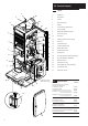
2.0 General Layout 2.1 1 2 3 22 Layout 1. Wallplate 2. Flue Elbow 3. Air Box 4. Heat Exchanger 5. Burner 6. Fan Protection Thermostat 7. Fan Assembly 8. DHW Plate Heat Exchanger 9. Three Way Valve 10. Facia Box 11. Primary Water Pressure Gauge 12. Gas Tap 13. Circulation Pump 14. Pressure Relief Valve 15. Return Thermistor 16. Gas/Air Ratio Valve 17. Transformer 18. Flow Temperature Safety Thermostat 19. Flow Temperature Thermistor 20. Manual Air Vent 21.
3.0 Appliance Operation NOTE: All delay timers mentioned in 3.1 and 3.2 are overridden by domestic hot water demand. 3.1 Central Heating Mode 1. With a demand for heating, the pump circulates water through the primary circuit. At a flow rate of approximately 4.5 l/hr the central heating flow switch operates, initiating the ignition sequence. 2. The burner ignites at low rate, then the gas control system modulates the heat input to maintain the heating temperature measured by the thermistor sensor. 3.
4.0 Technical Data Appliance Type C13 Appliance Category C33 CAT I 2H Heat Input Gross DHW Max kW 45.45 Btu/h 155,000 Heat Input Gross CH Max Factory Set kW 33.7 26.95 Btu/h 115,000 92,000 Heat Output CH Non Condensing (70°C Mean Water temp) Max Factory Set kW 30.0 23.9 Btu/h 102,000 81,500 Condensing (40°C Mean Water temp) Max Factory Set kW 31.4 25.1 Btu/h 107,000 85,600 Max Gas Rate (Natural Gas) (After 10 Mins) m3/h 4.2 ft3/h 148.
5.0 Dimensions and Fixings E 3° (1 in 20) C 490mm SIDE FLUE (left and right) For every 1m of horizontal flue length, the clearance above the top of the flue elbow should be 55mm to incorporate the 3° (1 in 20) fall in the flue from the terminal to the elbow. D 125mm Ø Min.
6.0 System Details 6.1 Information In GB it is necessary to comply with the Water Supply (Water Fittings) Regulations 1999 (or for Scotland, The Water Byelaws 2000, Scotland). The Baxi Combi 130 HE Combination Boiler is an Approved Product under the Water Regulations. To comply with the Water Regulations your attention is drawn to The Water Regulations Advisory Service (WRAS) which gives full details of the requirements. In IE the requirements given in the current edition of I.S.
6.0 System Details 6.3 System Control 1. The boiler is designed for use in a heating system that incorporates external controls, i.e. a minimum of a timer device. Double Stop Check Valve Valve 2. Suitable timer kits are available as optional extras. Stop Valve 3. For optimum operating conditions and maximum economy the fitting of the Baxi Intellistat, is recommended. 6.4 DHW Mains Inlet Temporary Hose CH Return System Filling and Pressurising 1.
6.0 System Details Other Tap Outlets 6.7 1. All DHW circuits, connections, fittings, etc. should be fully in accordance with relevant standards and water supply regulations. Boiler Expansion Vessel Domestic Hot Water Circuit 2.Your attention is drawn to: for GB: Guidance G17 to G24 and recommendation R17 to R24 of the Water Regulations Guide. for IE: the current edition of I.S. 813. "Domestic Gas Installations".
7.0 Site Requirements 7.1 1. The boiler may be fitted to any suitable nonflammable wall with the flue passing through an outside wall or roof and discharging to atmosphere in a position permitting satisfactory removal of combustion products and providing an adequate air supply. The boiler should be fitted within the building unless otherwise protected by a suitable enclosure i.e. garage or outhouse. (The boiler may be fitted inside a cupboard - see Section 7.2). Zone 2 Window Recess Zone 1 Zone 2 2.
7.0 Site Requirements 490mm 5mm Min 5mm Min 7.3 Clearances (Fig. 6 & 7) 1. A flat vertical area is required for the installation of the boiler. 200mm 2. These dimensions include the necessary clearances around the boiler for case removal, spanner access and air movement. Additional clearances may be required for the passage of pipes around local obstructions such as joists running parallel to the front face of the boiler. 7.4 850mm Gas Supply 1.
Termination to an internal soil and vent pipe Boiler 7.0 Site Requirements 7.6 Condensate Drain FAILURE TO INSTALL THE CONDENSATE DISCHARGE PIPEWORK CORRECTLY WILL AFFECT THE RELIABLE OPERATION OF THE BOILER 2.5° M inimum The condensate discharge pipe MUST NOT RISE at any point along its length. There MUST be a fall of AT LEAST 2.5° (50mm per metre) along the entire run. fall NOTE: It is unnecessary to fit an air break in the discharge pipe.
7.0 Site Requirements Terminal Position with Minimum Distance (Fig. 10) 7.7 (mm) Aa Directly below an opening, air brick, opening windows, etc. 300 Ba Above an opening, air brick, opening window etc. 300 Ca Horizontally to an opening, air brick, opening window etc. 300 D Below gutters, soil pipes or drain pipes. 25 E Below eaves. 25 F Below balconies or car port roof. 25 G From a vertical drain pipe or soil pipe. 25 (i) 25 (ii) 115 H From an internal (i) or external (ii) corner.
7.0 Site Requirements 7.8 m 0m 80 See Section 2.2. The standard horizontal flue kit allows for flue lengths between 270mm and 800mm from elbow to terminal (Fig. 11). mm 0 27 Flue Dimensions The maximum permissible equivalent flue length is: 4 metres horizontal (Fig. 12). NOTE: Each additional 45° of flue bend will account for an equivalent flue length of 0.5m. eg. 45° = 0.5m, 90° = 2 x 45° = 1m etc. 7.9 Terminal Guard (Fig. 13) 1.
7.0 Site Requirement A - Standard Flue 7.10 Flue options D Concentric The maximum equivalent lengths are 4m (horizontal) or 5m (vertical). These lengths exclude the standard elbow and flue/terminal assembly (horizontal) and terminal assembly (vertical). Twin Flue The total maximum equivalent flue length is 40m. NOTE: Each 1m of flue duct should be calculated as 2m. E Any additional “in line” bends in the flue system must be taken into consideration.
8.0 Installation 37.5mm Offset Note: For each 1m of horizontal flue add 55mm of clearance Centre for dia 150mm (6") hole for wall thickness 227mm (9") to 750mm (30") Centre for dia 125mm (5") hole for wall thickness upto 227mm (9") Centre line of flue at 3 Centre line of flue at 3 200mm Minimum Clearance Appliance outline Check Site Requirements (section 7.0) before commencing.
8.0 Installation 8.3 Lower Door Panel Outer Case Fixing Screw Preparing The Boiler 1. Remove the outer carton. 2. Remove the lower door panel (Fig. 16). 3. Remove the outer case fixing screws (Fig. 16). Slide the outercase upwards to disengage the hooks on the backplate and remove (Fig. 17). NOTE: Service Guidance Note Label is fitted to the inside of the outercase (Fig. 17). 4. Remove the sealing plugs from the copper bends. 5. Stand the boiler on its base by using the rear lower edge as a pivot. Fig.
8.0 Installation Top Hooks 8.4 Fitting The Boiler (Fig. 18) 1. Remove the tape from the tap rail on the support bracket. 2. Lift the boiler using the lower edges of the combustion box. 3. Lift the boiler over the support bracket and engage onto the top hooks. 4. To gain access to the connections between boiler and valves, release the facia securing screws (1/4 turn) and hinge down the facia box. 5. Make the connections in the following sequence: a) Gas connection first to centralise the boiler.
Wall Thickness 8.0 Installation 8.6 3° (1 in 20) Fitting The Flue Before fitting the flue, check the condensate drain integrity (see section 8.5). IMPORTANT: The flue should always be installed with a 3° (1 in 20) fall from terminal to elbow, to allow condensate to run back to the boiler. HORIZONTAL FLUE 1. The standard flue is suitable for lengths 270mm minimum to 800mm maximum (measured from the edge of the flue elbow outlet).
8.0 Installation 8.6 Inner Flue Support Bracket Fitting the Flue (Cont) 8. Ensure the inner flue support bracket is positioned in the flue (Fig. 24). 9. Engage the flue into the flue elbow using soap solution to ease the engagement ensuring the flue is assembled as shown (Fig. 25). Fig. 24 10. Place the gasket over the flue exit on the boiler (Fig. 25). 11. Slide the flue assembly through the hole in the wall. Ensure angled inner end slopes downwards (Fig. 26). Flue 12.
8.0 Installation 8.7 WARNING: This appliance must be earthed. L N Making The Electrical Connections 1. A plug is supplied with the boiler and the electrical connection is at the rear left hand side of the unit. Metal Shield Plug 2. Remove the electrical plug from the kit pack. Filter 3. Connect L, N & E into the plug and connect it to the socket at the rear left at the bottom of the boiler. 4. Remove the metal shield from the kit pack and connect it over the plug (Fig. 26a). Fig. 26a 5.
8.0 Installation 8.9 1. To fit a 2-wire thermostat, remove link and wire the thermostat switch between positions 1 & 2 (Figs. 30 or 31a). A cable clamp is provided for incoming cables. Mains Input Isolator Room Thermostat N 8.10 External Timer Fitting a Baxi Intellistat 1. Refer to the Baxi Intellistat instructions. L Filter Optional Live Feed For An External Pump N L N L 2.
9.0 Electrical 9.
9.0 Electrical 9.
Automatic Air Vent 10.0 Commissioning the Boiler 10.1 Commissioning the Boiler NOTE: The information shown on the display is explained on the label on the inside of the lower door panel (see Fig. 48). 1. Open the cold feed to the boiler. 2. Open all hot water taps to purge the Domestic Hot Water Circuit. Manual Air Vent 3. Ensure that the filling loop is connected and open, then open the heating flow and return valves on the boiler (see Section 10.5 Filling the System). Fig. 32 4.
10.0 10.2 Commissioning the Boiler Increasing Central Heating Output To 100,000 Btu/hr 1. The boiler is factory set for a maximum output of 80,000 Btu/hr. The boiler will automatically vary its output to match the system load giving the most efficient use of gas and the most comfortable room temperature possible. 2.
10.0 10.3 Commissioning the Boiler Switching Off Intelligent Pre-heat (cont) 5. To switch the pre-heat feature back on depress the “+” and “-” Temperature Control Buttons at the same time for 5 seconds. The display will show “18 or 10” (Fig. 39). 6. Press the Summer/Winter Mode Button marked ( ) and the display will show “20” (Fig. 40). The “2” indicates that the installer parameter for pre-heat has been selected. The “0” indicates that the pre-heat is switched off.
10.0 10.5 Commissioning the Boiler Filling the System 1. When filling the system move the diverter valve to the central heating position as follows (to ensure air is removed from manifold, wait until display shows ‘Of’):NOTE: If an additional pump has been fitted (see Section 8.12) disconnect the wiring until the system is filled and fully vented. 2. With mains switched on to the boiler press the “+” and “-” Temperature Control Buttons at the same time for 5 seconds. The display will show “18 or 10” (Fig.
11.0 Fitting the Outer Case 11.1 Fitting The Outer Case 1. Fit the outercase to the appliance ensuring that the four slots in the side flanges align with the hooks on the chassis (Fig. 48). 2. Insert the two fixing screws into the sides of the chassis (Fig. 49). 3. Locate the lower door panel on the studs on the case (Fig. 49). 4. Instruct the user in the operation of the boiler controls.
Flue Elbow 12.0 Servicing the Boiler 12.1 Annual Servicing IMPORTANT: When servicing ensure that both the gas and electrical supplies to the boiler are isolated before any work is started. Hazardous materials are not used in the construction of Baxi products, however reasonable care during service is recommended. 1. For reasons of safety and economy, it is recommended that the boiler is serviced annually. 2.
12.0 12.1 Servicing the Boiler Annual Servicing (Cont) NOTE: The information shown on the display is explained on the label on the inside of the lower door panel (see Fig. 48). Burner 12. To clean the heat exchanger and burner proceed as follows: a) Disconnect the electrical leads to the fan component protection sensor (Fig. 53). b) Undo the two wing nuts to disconnect the fan (Fig. 53). Injector Pipe c) Remove the fan and disconnect the electrical supply to it (Fig. 53).
13.0 Changing Components 13.1 Changing Components IMPORTANT: When changing components ensure that both the gas and electrical supplies to the boiler are isolated before any work is started. Hazardous materials are not used in the construction of Baxi products, however reasonable care during service is recommended. Heat Exchanger Manifold 1. Remove the outer case and lower door panel (see “Fitting the Outercase” Section 11.0). 2. Isolate the water circuit and drain the system as necessary.
13.0 Changing Components Flowswitch 13.3 Flow Pipe Flowswitch (Fig. 58) 1. Drain the boiler (see Section 13.1 paragraph 2 & 3). 2. It may be necessary to remove the expansion vessel (see Section 13.5). 3. Remove the clip securing the flow pipe to the flowswitch. Clip Fig. 58 4. Remove the two screws securing the flow switch to the boiler. 5. Disconnect the inline electrical connection. 6. Remove the flowswitch. 7. Fit the new flowswitch and reassemble in reverse order. 8.
13.0 Changing Components The pump, 3-way diverter valve, pressure gauge, pressure relief valve, plate heat exchanger and DHW flow switch can be accessed after hinging down the facia box. 1. Release the facia securing screws (1/4 turn) and hinge down the facia box (Fig. 61). 13.7 Pump (Fig. 61) 1. If only the head needs replacing, a standard Grundfos UPS 15-60 pump head is interchangeable (see section 13.9 for details). Facia Box 2. This must be switched to setting No 3 (Fig. 62). 13.
13.0 Changing Components 13.10 Three-Way Diverter Valve (Head Only) (Fig. 65) If only the head needs replacing: 1. Unplug the wiring harness from the 3-way diverter valve. 2.Depress the clip and revolve the head through 30° and remove. 3. Fit replacement head and reassemble in reverse order. 13.11 Three-Way Diverter Valve (Complete) (Fig. 66) 1. Drain the boiler (see Section 13.1 paragraph 2 & 3). Three-Way Diverter Valve Head 2. Unplug the wiring harness from the 3-way diverter valve. 3.
13.0 Changing Components 13.12 Pressure Gauge (Fig. 67) Pressure Gauge Bracket 1. Drain the boiler (see Section 13.1 paragraph 2 & 3). 2. Undo the nut retaining the capillary in the connection at the return pipe (Fig. 68). 3. Depress the two lugs on either side of the pressure gauge and feed through the bracket. 4. Fit new pressure gauge and reassemble in reverse order. Pressure Gauge Lug 13.13 Pressure Relief Valve (Fig. 69) 1.
13.0 Changing Components 13.14 DHW Plate Heat Exchanger 1. Drain the boiler (see Section 13.1 paragraph 2 & 3). 2. Remove the four screws securing the plate heat exchanger to the manifolds (Fig. 70). NOTE: Ensure nuts are not dislodged from the manifolds. 3. Remove the plate heat exchanger cover (Fig. 71) 4. Remove the ’O’ rings from the manifolds and replace with new ‘O’ rings (Fig. 71). 5.
13.0 Changing Components The control, display and fan driver boards can be accessed on the removal of the main electrical box cover. 1. Release the facia securing screws (1/4 turn) and hinge down the facia box. 2. Remove the screws securing the main electrical box cover (Fig. 73) and rotate the cover upwards to gain access. 13.16 Control Board (Fig. 73) 1. Remove the screws securing the control board and disconnect the electrical connections noting their positions although they are one way fitting.
13.0 Changing Components The fan and venturi, gas valve, injector pipe, condensate trap, fan protection thermostat, spark and sensing electrodes can be accessed and changed on the removal of the airbox door panel. 1. Remove the airbox door panel by loosening the four 1/4 turn screws (Fig. 75). 13.20 Spark and Sensing Electrodes Air Box Door Panel (Fig. 76) 1. Disconnect the leads to the electrodes noting their positions (left to right): Spark Opaque Lead Spark Opaque Lead Sensing White Lead 2.
13.0 Changing Components It is necessary to remove the fan before changing the injector pipe, condensate trap and gas valve (see section 13. 21). 13.22 Injector Pipe (Fig. 78) 1. Remove the injector pipe by pulling out from the ‘O’ ring joint in the gas valve. 2. Fit the new injector pipe and reassemble in reverse order, applying Greasil 4000 (Approved Silicone Grease) to both “O” rings. 13.23 Gas Valve (Fig. 78) Injector Pipe 1. Release the facia securing screws 1/4 turn and hinge down the facia box.
13.0 Changing Components Heat Exchanger Support Bolt The burner and heat exchanger can be changed after removal of the combustion box door. To change the heat exchanger, the fan and burner must be removed first (see section 13. 21 & 13. 25). Burner 1. Remove the combustion box door by undoing the four 1/4 turn securing screws. 13.25 Burner (Fig. 80) WARNING: The burner skin is fragile: (HANDLE WITH CARE) 1. Remove the two 8mm hex head screws securing the burner to the base of the combustion box.
13.0 Changing Components 13.27 Heat Exchanger Insulation Pads (Fig. 84) 1. Remove the fan and condensate trap (see section 13.21 and 13.24). 2. Remove the burner (see section 13. 25). 3. Remove the four bolts securing the combustion box base. 4. Remove the combustion box base. 5. Pull the central insulation panel down from the centre of the heat exchanger and remove the insulation pads. 6. Check combustion box seal for damage, replace if necessary. Central Insulation Panel 7.
14.0 Short Parts List Short Parts List C A K Key No. G.C. No. Description Manufacturers Part No.
Before performing fault finding carry out preliminary electrical checks for earth, continuity and polarity. See Section 8.13 YES Display Blank ? NO Display Showing 00 ? YES NO Display Showing OF ? YES Go to No Display section of the fault finding instructions. Check stats at top right of boiler. Red wires go to red stat, black wires to black stat.Check integral timer wires exit PCB cover at right hand side (not run over Main PCB). Central Heating switched off.
No Display 240 V at A ? NO 15.0 Fault Finding Ensure that mains is securely connected to incoming plug and that wiring from electrical filter to boiler 8-way terminal block is OK. Prog Prog R/S R/S YES L N 240 V at B ? NO 1 2 1 2 Extra Pump Check wiring from boiler 8-way terminal block to PCB is OK. A YES Main PCB Fuse OK ? NO Check for shorts on Pump, Diverter Valve, Fan and Gas Valve, then replace fuse. YES 240 V at C ? NO Replace Main PCB.
Ignition Lockout 15.0 Fault Finding Gas Valve Plug (when unplugged) NO Is there gas at gas valve inlet ? F Check isolation valve and gas supply. YES NO Reset Lockout. When the Burner On light is on, is there gas flow (check at meter) ? NO Remove Gas Valve & check inlet filter for blockage. Check gas feed pipe seals, venturi gasket & fan seals are fited and not damaged. Otherwise incorrect gas supply to boiler.
Dry-Fire Fault (L7 or L8) 15.0 Fault Finding Plug from PCB to Pump (when unplugged) Is the system full of water ? NO Fill system with water and bleed out all air. J YES With water flowing out of a full open DHW tap, does the Pump run ? NO Unplug the pump, is there 240V at J? NO YES YES With water flowing out of a fully open DHW tap, is there continuity at L ? NO Is there 240V at K? Replace PCB. YES Pump Fault (water in pump housing terminals ?).
Fan (L9) Is there at least 24Vdc at M ? 15.0 Fault Finding NO Replace Main PCB. Transformer Mains Input YES When display shows 12 or 22, is there at least 2Vdc at N ? Flow & Return Thermistors Burner On & Fault Neons NO Replace Main PCB. Pump Overheat Thermostats & Flow Switches & Condensate Trap YES Diverter Valve Is there at least 24Vdc at O ? NO N Wiring from Main PCB to Fan PCB faulty.
Flow Temperature Overheat Lockout (Ld) or Fan Temperature Overheat Lockout (LE) Display flashing Ld ? YES NO Replace stat. YES Reconnect stat. Disconnect 9-way PCB connector. Is there continuity across T ? Fault Finding Display flashing LE ? YES Disconnect black stat on flow pipe. When flow < 60° C, is there continuity across stat ? 15.0 Disconnect Fan Stat. When Fan temperature < 60° C, is there continuity across stat ? Replace stat. YES NO Wiring from PCB to thermostats faulty.
Condensate Trap (LF) or DHW Flow Switch (Lt) 15.0 Display flashing LF ? Display flashing Lt ? YES Is Condensate Trap blocked or water on terminals ? YES Clear blockage and dry sensors. Fit secondary trap and air break if connected to internal stack/soil pipe. Disconnect drain and run boiler to prove. If fault persists change condensate trap faulty. NO Unplug 9-way PCB connector. Is there continuity from V to earth ? Fault Finding YES Unplug 9-way connector from PCB.
15.0 Burner or Heat Exchanger Noisy Is the noise coming from the burner ? Fault Finding Is the noise coming from the heat exchanger ? YES YES YES Is the Burner damaged ? Ensure that there is no air in the heat exchanger or system. Replace Burner. NO YES Is the Burner Seal missing or damaged ? Is the Expansion Vessel charged (1 bar nominal) ? YES Fit new Burner Seal. YES NO Is the Burner loose ? YES Add extra inhibitor to system. Tighten Burner connections.
15.0 DHW Fault Fault Finding Replace DHW Flow Switch. NO Set to summer mode (display shows Of). With water flowing out of a fully open DHW tap does display show Of ? YES Unplug 9-way connector from PCB. With water flowing out of a fully open DHW tap is there continuity across A ? NO YES Unplug DHW F/S inline connector. With water flowing out of a fully open tap is there continuity across A? NO Is DHW Flow Switch blocked ? YES YES Replace PCB. Wiring from PCB to Flow Switch faulty.
15.0 Central Heating Is there an Intellistat connected to the boiler ? YES Go to Intellistat section of the fault finding instructions. Fault Finding YES Is there 240V from Q to R & from R to S ? NO Wiring from PCB to Diverter Valve faulty. Diverter Valve Plug (when unplugged) NO NO PCB faulty. PCB faulty. Is there 240V from Neutral to H ? N YES P NO Is there 240V from Neutral to I ? Wiring from PCB to Prog 1 faulty.
15.0 Intellistat Fault Finding Wiring from boiler to Intellistat faulty. YES YES Is the Intellistat display blank ? Hinge down the flap below the Intellistat display. Press the Intellistat Reset Button.
16.0 Operational Flow Chart 16.1 Domestic Hot Water Mode DHW Flow Switch off & Flow temp above 55°C OFF DHW Flow Switch on or Flow temp below preheat level. (Overrun done & DHW Flow Switch off) or (DHW Flow Switch off & Flow temp ≥ 55°C). DHW OVERRUN Pump on (DHW Flow Switch off & Flow temp below 55°C & Flow temp above preheat level) or DHW temp 10°C above set point DHW RUN Pump on Fan speed variable Gas Valve on DHW Flow Switch on & DHW temp below set point.
16.0 Operational Flow Chart 16.
BAXI POTTERTON A Trading Division of Baxi Heating UK Ltd Brownedge Road Bamber Bridge Preston Lancashire PR5 6SN After Sales Service 08706 096 096 Technical Enquiries 08706 049 049 Website www.baxi.co.