
Technical data

13.0 Changing Components
36
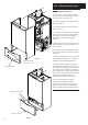
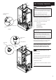
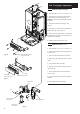
13.3 Flowswitch (Fig. 58)
1. Drain the boiler
(see Section 13.1 paragraph 2 & 3).
2. It may be necessary to remove the expansion
vessel (see Section 13.5).
3. Remove the clip securing the flow pipe to the
flowswitch.
4. Remove the two screws securing the flow
switch to the boiler.
5. Disconnect the inline electrical connection.
6. Remove the flowswitch.
7. Fit the new flowswitch and reassemble in
reverse order.
8. Recommission the boiler and check the
inhibitor concentration (see Section 6.2 and 10.1).
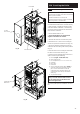
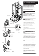
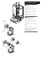
13.4 Flow or Return Temperature
Thermistors and Safety Thermostat
(Figs. 59 & 59a)
1. The procedure is the same for both the
thermistors and the safety thermostat, although
the components are not interchangeable.
2. Remove the electrical connections from the
component.
3. Unscrew the component from the pipe.
4. Fit the new thermistor or safety thermostat and
reassemble in reverse order.
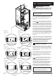
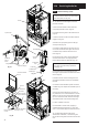
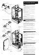
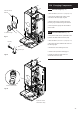
13.5 Expansion Vessel (Fig. 60)
1. Drain the boiler (see Section 13.1 paragraph 2 & 3).
2. Loosen the securing screw at the base of the
expansion vessel.
3. Whilst supporting the vessel undo the
expansion vessel connection and retain the
sealing washer.
4. Remove the expansion vessel.
5. Fit the new expansion vessel and reassemble
in reverse order.
13.6 Re-pressuring Expansion vessel
1. The charge pressure is 1.0 bar.
2. Close the central heating flow and return
isolating valves.
3. Drain the boiler
(see Section 13.1 paragraph 2 & 3).
4. The “Schraeder” valve is positioned centrally at
the side of the appliance. Pressurise to 1.0 bar.
5. Open the isolating valves and recharge the
system to between 1.0 bar and 2.5 bar. Vent the
system as necessary.
Fig. 58
Flowswitch
Clip
Fig. 59
Fig. 60
Flow Pipe
Electrical
Connections
Expansion Vessel
Expansion Vessel
Securing Screw
Flow Thermistor (Red Body)
Safety Thermostat (Black Body)
Expansion Vessel
Connection
ReturnThermistor
(Red Body)
Fig. 59a